How to Use cáp bus 3 pin xh2.54mm: Examples, Pinouts, and Specs
Introduction
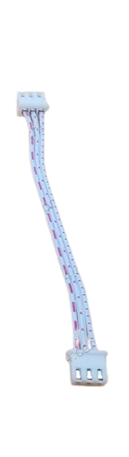
The 3-pin bus cable with XH2.54mm connectors is a versatile and widely used component in electronics. It features a 2.54mm pitch connector, making it compatible with a variety of devices, including sensors, modules, and microcontrollers. This cable is ideal for establishing reliable connections in low-power circuits and is commonly used in prototyping, robotics, and IoT applications.
Explore Projects Built with cáp bus 3 pin xh2.54mm

Explore Projects Built with cáp bus 3 pin xh2.54mm
Common Applications and Use Cases
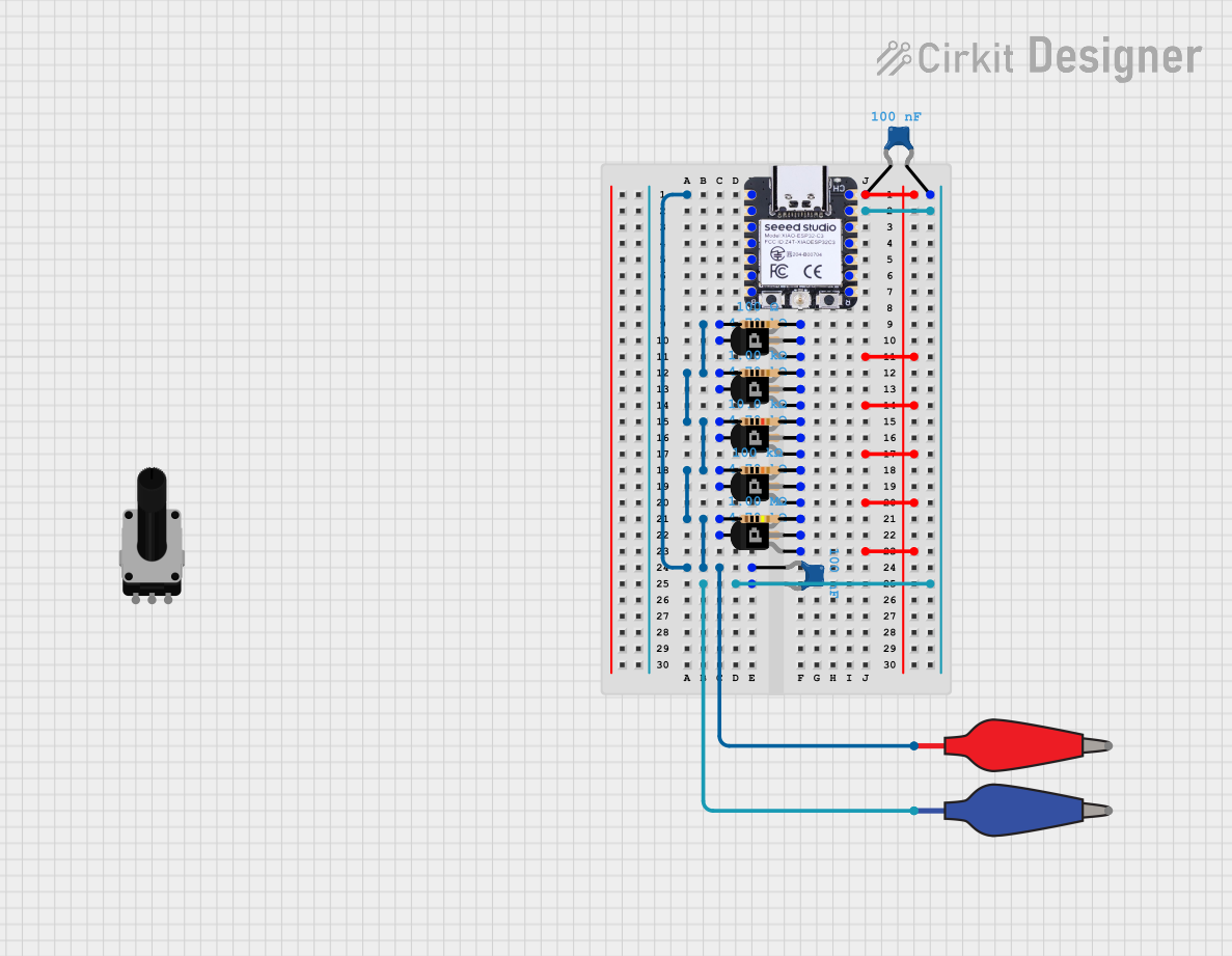
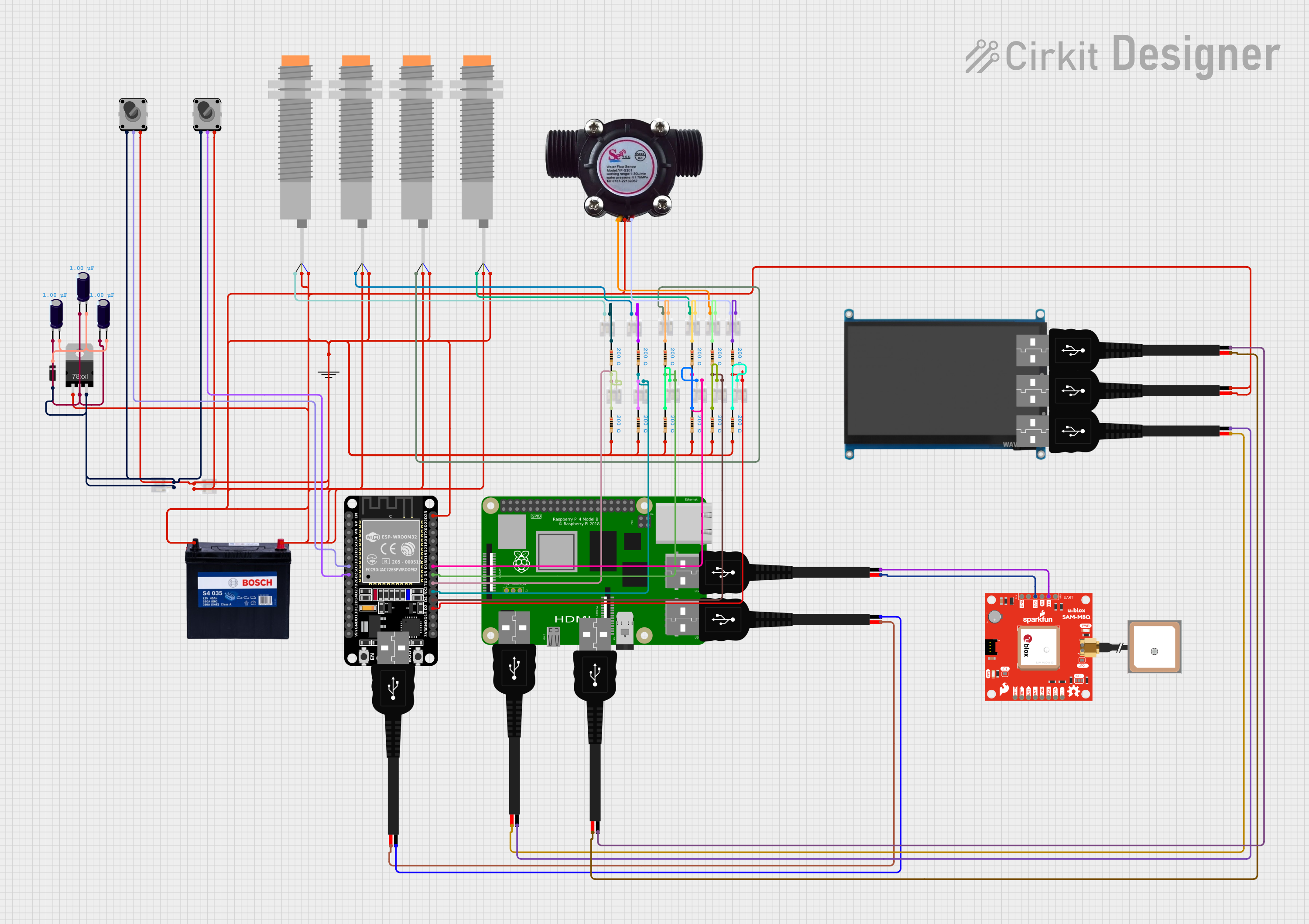
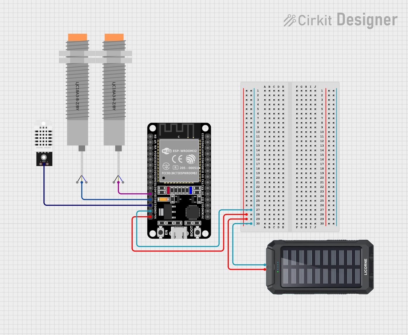
- Connecting sensors and modules to microcontrollers (e.g., Arduino, Raspberry Pi)
- Powering small electronic devices
- Signal transmission in low-power circuits
- Prototyping and testing electronic designs
Technical Specifications
The following are the key technical details of the 3-pin bus cable with XH2.54mm connectors:
| Parameter | Specification |
|---|---|
| Connector Type | XH2.54mm |
| Number of Pins | 3 |
| Pitch (Pin Spacing) | 2.54mm |
| Cable Length | Typically 10cm to 30cm (varies) |
| Wire Gauge | 26 AWG |
| Maximum Voltage Rating | 250V |
| Maximum Current Rating | 3A |
| Insulation Material | PVC |
| Operating Temperature | -25°C to 85°C |
Pin Configuration and Descriptions
The 3-pin bus cable typically follows the standard pinout configuration:
| Pin Number | Label | Description |
|---|---|---|
| 1 | VCC | Power supply (e.g., 3.3V or 5V) |
| 2 | GND | Ground |
| 3 | Signal | Data or control signal |
Note: The pinout may vary depending on the device or module being connected. Always refer to the datasheet or documentation of the connected device.
Usage Instructions
How to Use the Component in a Circuit
- Identify the Pinout: Verify the pinout of the XH2.54mm connector and ensure it matches the device or module you are connecting to.
- Connect to the Circuit:
- Plug the XH2.54mm connector into the corresponding header on the device or module.
- Ensure the VCC, GND, and Signal pins are correctly aligned.
- Secure the Connection: If necessary, use additional measures (e.g., cable ties) to secure the cable and prevent accidental disconnection.
- Power the Circuit: Once all connections are made, power the circuit and test the functionality.
Important Considerations and Best Practices
- Voltage and Current Ratings: Ensure the cable is used within its maximum voltage (250V) and current (3A) ratings to avoid damage.
- Pin Alignment: Double-check the pin alignment to prevent reverse polarity or incorrect connections.
- Cable Length: Use an appropriate cable length to minimize signal degradation or power loss.
- Environmental Conditions: Avoid exposing the cable to extreme temperatures or moisture to maintain its durability.
Example: Connecting to an Arduino UNO
The 3-pin bus cable can be used to connect a sensor (e.g., temperature sensor) to an Arduino UNO. Below is an example of how to use the cable in a circuit:
Circuit Setup
- Connect the VCC pin of the cable to the 5V pin on the Arduino.
- Connect the GND pin of the cable to the GND pin on the Arduino.
- Connect the Signal pin of the cable to an appropriate digital or analog pin on the Arduino (e.g., A0).
Arduino Code Example
// Example code for reading a sensor connected via a 3-pin XH2.54mm cable
// The sensor's signal pin is connected to Arduino analog pin A0

const int sensorPin = A0;  // Define the analog pin for the sensor
int sensorValue = 0;       // Variable to store the sensor reading

void setup() {
  Serial.begin(9600);  // Initialize serial communication at 9600 baud
  pinMode(sensorPin, INPUT);  // Set the sensor pin as an input
}

void loop() {
  sensorValue = analogRead(sensorPin);  // Read the sensor value
  Serial.print("Sensor Value: ");       // Print the sensor value to the serial monitor
  Serial.println(sensorValue);
  delay(1000);  // Wait for 1 second before the next reading
}
Note: Modify the code as needed based on the specific sensor or module being used.
Troubleshooting and FAQs
Common Issues and Solutions
Loose Connection:
- Issue: The cable is not securely connected, causing intermittent signals.
- Solution: Ensure the connector is fully inserted into the header and secured.
Incorrect Pinout:
- Issue: The VCC, GND, or Signal pins are misaligned.
- Solution: Double-check the pinout of the connected device and align the pins correctly.
Signal Interference:
- Issue: The signal is noisy or unstable.
- Solution: Use a shorter cable or add a decoupling capacitor near the device.
Cable Damage:
- Issue: The cable is physically damaged, leading to poor performance.
- Solution: Replace the cable with a new one.
FAQs
Q1: Can this cable be used for high-power applications?
A1: No, the cable is designed for low-power applications with a maximum current rating of 3A.
Q2: Is the cable compatible with breadboards?
A2: Yes, the XH2.54mm connector can be used with compatible headers on breadboards or PCBs.
Q3: Can I extend the cable length?
A3: Yes, but longer cables may introduce signal degradation. Use shielded cables for longer distances if necessary.
Q4: How do I clean the connectors?
A4: Use a soft brush or compressed air to remove dust. Avoid using liquids that may damage the insulation.