How to Use upswave: Examples, Pinouts, and Specs
Introduction
The UPSWave is a waveform generated by an Uninterruptible Power Supply (UPS) to provide backup power during electrical outages. It ensures a continuous power supply to connected devices, preventing data loss, hardware damage, or operational interruptions. The UPSWave is typically available in two forms: modified sine wave and pure sine wave.
- Modified Sine Wave: A stepped approximation of a sine wave, suitable for less sensitive devices.
- Pure Sine Wave: A smooth, continuous waveform identical to utility power, ideal for sensitive electronics.
Explore Projects Built with upswave
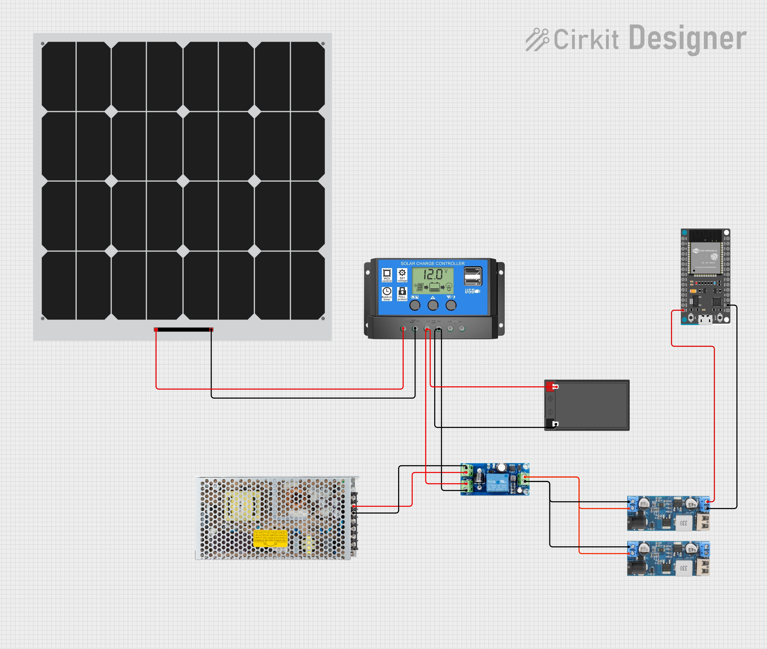


Explore Projects Built with upswave
Common Applications and Use Cases
- Computers and Servers: Prevents data loss and hardware damage during power outages.
- Home Appliances: Powers devices like refrigerators, fans, and lights during blackouts.
- Medical Equipment: Ensures uninterrupted operation of critical devices.
- Industrial Systems: Maintains power for automation and control systems.
- Telecommunication: Keeps routers, modems, and communication systems operational.
Technical Specifications
Key Technical Details
| Parameter | Value/Description |
|---|---|
| Waveform Type | Modified Sine Wave or Pure Sine Wave |
| Input Voltage Range | 100V - 240V AC |
| Output Voltage | 110V or 220V AC (depending on model) |
| Frequency | 50Hz or 60Hz |
| Power Rating | 300W to 3000W (varies by UPS model) |
| Efficiency | Up to 95% |
| Battery Type | Sealed Lead Acid (SLA) or Lithium-Ion |
| Transfer Time | <10ms (typical) |
| THD (Total Harmonic Distortion) | <3% for pure sine wave, <25% for modified sine wave |
Pin Configuration and Descriptions
The UPSWave is not a discrete electronic component with pins but is part of a UPS system. However, the following table describes the key input/output connections typically found on a UPS:
| Pin/Port Name | Description |
|---|---|
| AC Input | Connects to the main power supply (100V-240V AC). |
| AC Output | Provides backup power to connected devices. |
| Battery Terminals | Connects to the internal or external battery. |
| USB/Serial Port | For communication with a computer or monitoring system. |
| Ground (GND) | Ensures safety and proper grounding of the system. |
Usage Instructions
How to Use the UPSWave in a Circuit
Connect the UPS to the Main Power Supply:
- Plug the UPS into a standard AC wall outlet (100V-240V AC).
- Ensure the input voltage matches the UPS specifications.
Connect Devices to the UPS Output:
- Plug your devices into the AC output sockets of the UPS.
- For sensitive electronics, use a pure sine wave UPSWave for better compatibility.
Monitor Battery Status:
- Check the battery charge level using the UPS display or monitoring software.
- Replace the battery as per the manufacturer's recommendations.
Test the UPSWave:
- Simulate a power outage by disconnecting the UPS from the main power supply.
- Verify that the connected devices continue to operate without interruption.
Important Considerations and Best Practices
- Choose the Right Waveform: Use a pure sine wave UPSWave for sensitive electronics like computers, medical equipment, and audio systems.
- Avoid Overloading: Ensure the total power consumption of connected devices does not exceed the UPS's power rating.
- Regular Maintenance: Periodically test the UPS and replace the battery as needed.
- Ventilation: Place the UPS in a well-ventilated area to prevent overheating.
- Grounding: Properly ground the UPS to avoid electrical hazards.
Example: Connecting a UPSWave to an Arduino UNO
To power an Arduino UNO during a power outage, connect the UPSWave output to a 5V DC adapter. Below is an example Arduino sketch to monitor the UPS status via a serial connection:
// Arduino code to monitor UPS status via serial communication
// Ensure the UPS is connected to the Arduino via a USB or serial port

void setup() {
  Serial.begin(9600); // Initialize serial communication at 9600 baud
  pinMode(13, OUTPUT); // Set pin 13 as an output for status indication
}

void loop() {
  if (Serial.available() > 0) {
    String upsStatus = Serial.readString(); // Read UPS status from serial
    Serial.println("UPS Status: " + upsStatus); // Print status to serial monitor

    if (upsStatus.indexOf("Battery Low") != -1) {
      digitalWrite(13, HIGH); // Turn on LED if battery is low
    } else {
      digitalWrite(13, LOW); // Turn off LED otherwise
    }
  }
  delay(1000); // Wait for 1 second before checking again
}
Troubleshooting and FAQs
Common Issues and Solutions
| Issue | Possible Cause | Solution |
|---|---|---|
| Devices not powering on | UPS is overloaded or battery is discharged | Reduce load or recharge/replace the battery. |
| Frequent beeping | Low battery or overload condition | Check battery status and reduce connected load. |
| UPS overheating | Poor ventilation or excessive load | Ensure proper airflow and reduce load if necessary. |
| No output during outage | Faulty battery or inverter circuit | Test and replace the battery or contact support. |
FAQs
What is the difference between a modified sine wave and a pure sine wave?
- A modified sine wave is a stepped approximation of a sine wave, suitable for basic devices. A pure sine wave is smooth and continuous, ideal for sensitive electronics.
Can I use a UPSWave with a refrigerator or air conditioner?
- Yes, but ensure the UPS has sufficient power capacity and uses a pure sine wave for compatibility with motor-driven appliances.
How often should I replace the UPS battery?
- Typically every 3-5 years, depending on usage and battery type.
Why does my UPS beep continuously?
- This usually indicates a low battery, overload, or fault condition. Check the UPS manual for specific beep codes.
By following this documentation, you can effectively use and maintain a UPSWave to ensure uninterrupted power for your devices.