
How to Use Amplifier: Examples, Pinouts, and Specs
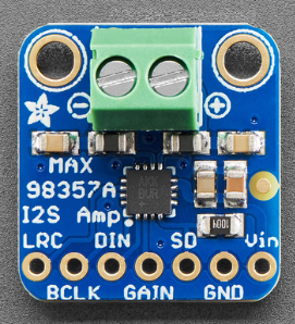
 Design with Amplifier in Cirkit Designer
Introduction
The MAX98357 is a digital input, Class D audio amplifier manufactured by GODIYMODULES. It is designed to efficiently amplify audio signals while maintaining high sound quality. This amplifier is particularly well-suited for applications requiring compact, low-power, and high-performance audio solutions. It supports I2S (Inter-IC Sound) digital audio input, making it ideal for modern audio systems.
Explore Projects Built with Amplifier
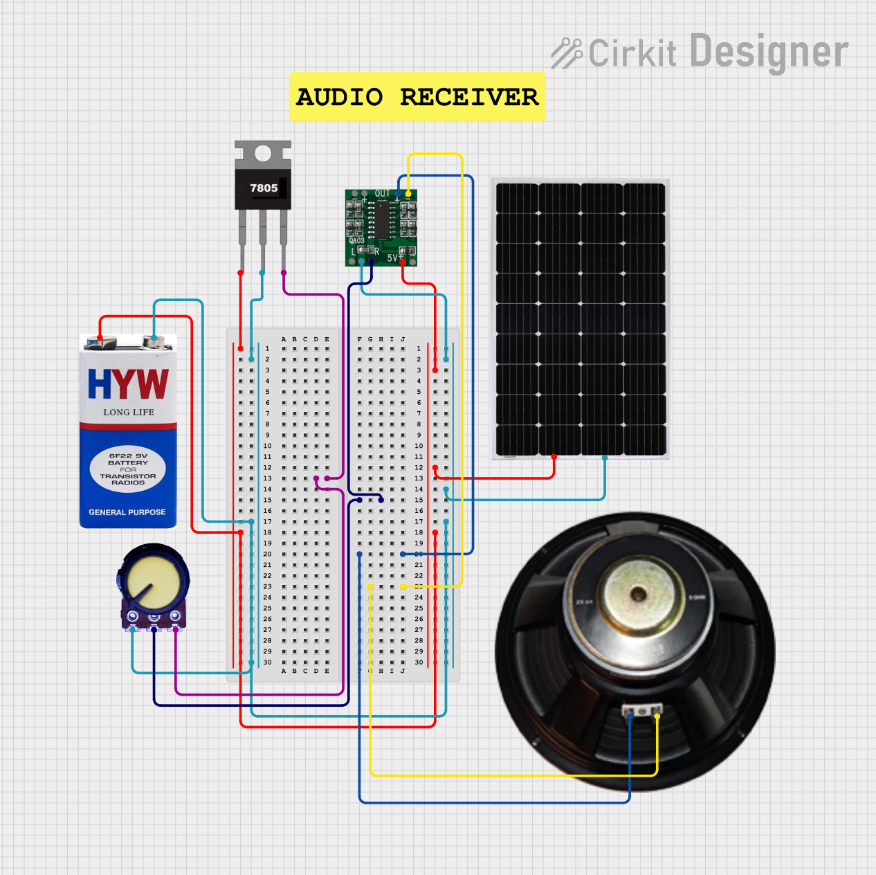 Open Project in Cirkit Designer
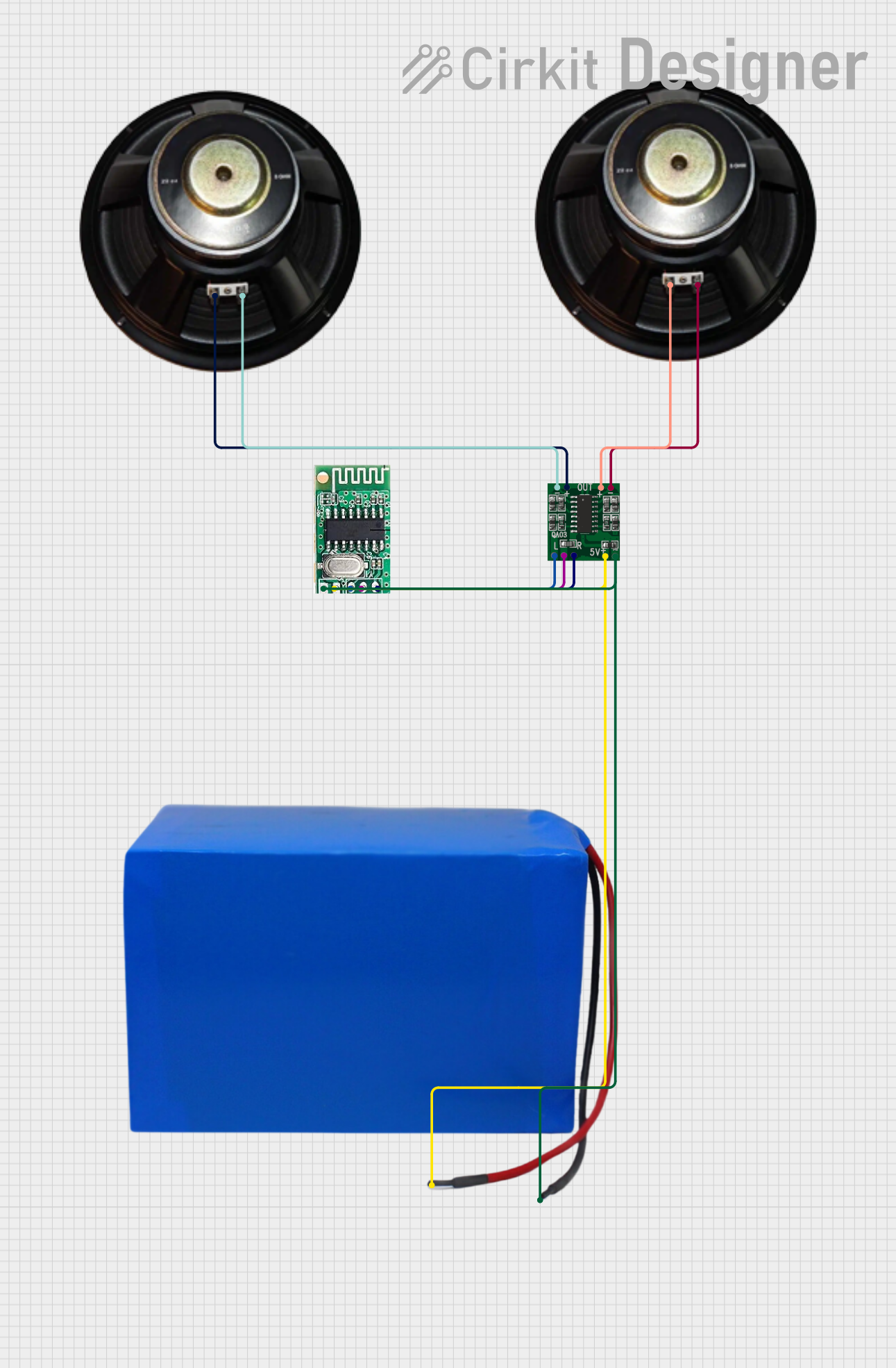 Open Project in Cirkit Designer
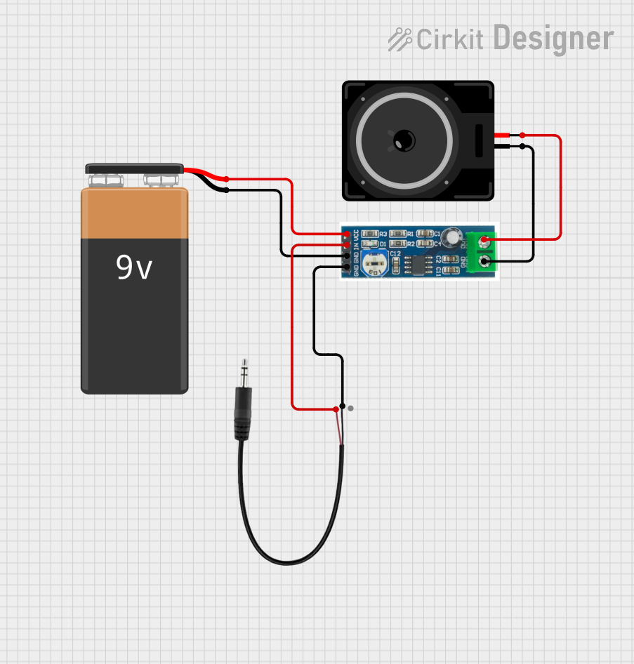 Open Project in Cirkit Designer
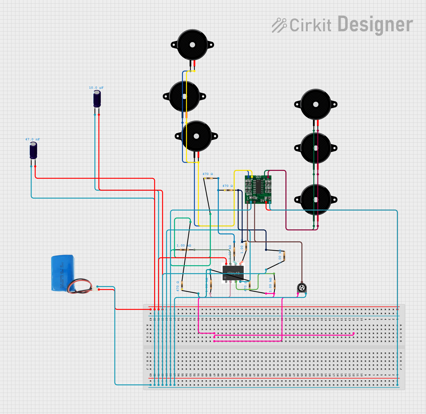 Open Project in Cirkit Designer
Explore Projects Built with Amplifier
Open Project in Cirkit DesignerOpen Project in Cirkit DesignerOpen Project in Cirkit DesignerOpen Project in Cirkit DesignerCommon Applications and Use Cases
- Portable audio devices
- Smart speakers
- IoT devices with audio output
- Home automation systems
- Audio signal processing projects
- Arduino and Raspberry Pi audio projects
Technical Specifications
The MAX98357 amplifier is a highly efficient and versatile component. Below are its key technical details:
Key Technical Details
| Parameter | Value |
|---|---|
| Manufacturer | GODIYMODULES |
| Part ID | MAX98357 |
| Amplifier Type | Class D |
| Input Type | I2S Digital Audio |
| Output Power | Up to 3.2W at 4Ω load, 10% THD+N |
| Supply Voltage Range | 2.5V to 5.5V |
| Efficiency | Up to 92% |
| Signal-to-Noise Ratio | 98 dB |
| Supported Sampling Rates | 8 kHz to 96 kHz |
| Shutdown Current | 0.2 µA (typical) |
| Operating Temperature | -40°C to +85°C |
Pin Configuration and Descriptions
The MAX98357 module typically comes with the following pin configuration:
| Pin Name | Pin Type | Description |
|---|---|---|
| VIN | Power Input | Power supply input (2.5V to 5.5V). Connect to a stable power source. |
| GND | Ground | Ground connection. |
| BCLK | Digital Input | Bit clock for I2S communication. |
| LRCLK | Digital Input | Left/Right clock for I2S communication. |
| DIN | Digital Input | Data input for I2S audio signal. |
| SD | Digital Input | Shutdown pin. Pull low to disable the amplifier; pull high to enable it. |
| OUT+ | Output | Positive speaker output. |
| OUT- | Output | Negative speaker output. |
Usage Instructions
The MAX98357 amplifier is straightforward to use in audio projects. Below are the steps and considerations for integrating it into your circuit:
How to Use the MAX98357 in a Circuit
- Power Supply: Connect the VIN pin to a stable power source (2.5V to 5.5V) and the GND pin to ground.
- I2S Audio Input:
- Connect the BCLK, LRCLK, and DIN pins to the corresponding I2S output pins of your microcontroller or audio source.
- Ensure the I2S configuration matches the amplifier's supported sampling rates (8 kHz to 96 kHz).
- Speaker Connection:
- Connect the OUT+ and OUT- pins to the terminals of a speaker (4Ω or 8Ω impedance is recommended).
- Shutdown Control:
- Use the SD pin to enable or disable the amplifier. Pull it high to enable or low to disable.
- Decoupling Capacitors: Place decoupling capacitors (e.g., 10 µF and 0.1 µF) near the VIN pin to stabilize the power supply.
Important Considerations and Best Practices
- Use a heat sink or ensure proper ventilation if operating at high power levels for extended periods.
- Avoid connecting the amplifier to a power source exceeding 5.5V to prevent damage.
- Ensure the I2S signal is properly configured to avoid audio distortion or malfunction.
- Use a speaker with the recommended impedance (4Ω or 8Ω) for optimal performance.
Example: Connecting MAX98357 to an Arduino UNO
Below is an example of how to connect the MAX98357 to an Arduino UNO and play audio using the I2S protocol.
Wiring Diagram
| MAX98357 Pin | Arduino UNO Pin |
|---|---|
| VIN | 5V |
| GND | GND |
| BCLK | Pin 9 |
| LRCLK | Pin 10 |
| DIN | Pin 11 |
| SD | 5V (via 10kΩ pull-up resistor) |
Arduino Code Example
#include <I2S.h> // Include the I2S library for audio communication

void setup() {
  // Initialize I2S with 44.1 kHz sampling rate and 16-bit resolution
  if (!I2S.begin(I2S_PHILIPS_MODE, 44100, 16)) {
    Serial.println("Failed to initialize I2S!");
    while (1); // Halt execution if I2S initialization fails
  }
  Serial.println("I2S initialized successfully.");
}

void loop() {
  // Generate a simple sine wave for testing
  for (int i = 0; i < 360; i++) {
    float sample = sin(i * PI / 180); // Calculate sine wave value
    int16_t audioSample = (int16_t)(sample * 32767); // Scale to 16-bit range
    I2S.write(audioSample); // Send audio sample to MAX98357
  }
}
Troubleshooting and FAQs
Common Issues and Solutions
No Sound Output:
- Verify that the SD pin is pulled high to enable the amplifier.
- Check the I2S connections and ensure the audio source is configured correctly.
- Ensure the speaker is properly connected to the OUT+ and OUT- pins.
Distorted Audio:
- Confirm that the I2S sampling rate matches the audio source's configuration.
- Check for loose or incorrect wiring.
- Ensure the power supply voltage is stable and within the specified range.
Overheating:
- Reduce the output power or use a heat sink to dissipate heat.
- Ensure proper ventilation around the amplifier.
FAQs
Q: Can the MAX98357 drive headphones?
A: No, the MAX98357 is designed to drive speakers with an impedance of 4Ω or 8Ω. It is not suitable for headphones.
Q: What is the maximum sampling rate supported by the MAX98357?
A: The MAX98357 supports sampling rates from 8 kHz to 96 kHz.
Q: Can I use the MAX98357 with a 3.3V microcontroller?
A: Yes, the MAX98357 is compatible with 3.3V logic levels and can operate with a 3.3V power supply.
Q: Is an external DAC required to use the MAX98357?
A: No, the MAX98357 has a built-in DAC and accepts I2S digital audio input directly.