Cirkit Designer Logo
Cirkit Designer
Your all-in-one circuit design IDE
Home / 
Component Documentation

How to Use pzem-004t: Examples, Pinouts, and Specs

Image of pzem-004t
Cirkit Designer LogoDesign with pzem-004t in Cirkit Designer

Introduction

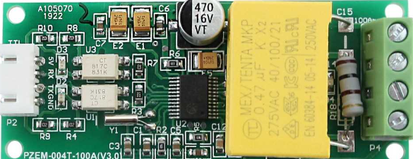
The PZEM-004T is a digital power meter designed for monitoring and measuring key electrical parameters in AC circuits. It can measure voltage, current, power, energy, and frequency with high accuracy. This module communicates via UART (Universal Asynchronous Receiver-Transmitter), making it easy to interface with microcontrollers such as the Arduino UNO. Its compact design and reliable performance make it a popular choice for energy monitoring, home automation, and industrial applications.

Explore Projects Built with pzem-004t

Use Cirkit Designer to design, explore, and prototype these projects online. Some projects support real-time simulation. Click "Open Project" to start designing instantly!
ESP32-Based Smart Environmental Monitoring System with Relay Control
Image of SOCOTECO: A project utilizing pzem-004t in a practical application
This is a smart environmental monitoring and control system featuring an ESP32 microcontroller interfaced with a PZEM004T for power monitoring, relay modules for actuating bulbs and a fan, and an LCD for user interface. It includes flame, gas, and vibration sensors for safety monitoring purposes.
Cirkit Designer LogoOpen Project in Cirkit Designer
ESP32-Controlled AC Lighting System with Power Monitoring
Image of Smart Energy Meter: A project utilizing pzem-004t in a practical application
This circuit features an ESP32 microcontroller interfaced with a PZEM004T power monitoring module and a 4-channel relay module controlling multiple AC LED bulbs. The ESP32 uses GPIO pins to control the relays, which in turn switch the LED bulbs on and off. The PZEM004T is connected to the ESP32 for communication and to a current sensor for monitoring power consumption of the connected load through the relay contacts.
Cirkit Designer LogoOpen Project in Cirkit Designer
ESP8266 NodeMCU Based Energy Monitoring Display with PZEM004T and OLED Screen
Image of Energy Consumption Monitoring: A project utilizing pzem-004t in a practical application
This circuit is designed to monitor electrical parameters using the PZEM004t sensor and display the data on a 0.96" OLED screen. The esp8266 nodemcu serves as the central controller, interfacing with the PZEM004t sensor via serial communication (RX/TX) and with the OLED display through an I2C connection (SCK/SDA). A 5V adapter provides power to the circuit, with the nodemcu regulating down to 3.3V for the OLED display and the PZEM004t sensor receiving 5V directly.
Cirkit Designer LogoOpen Project in Cirkit Designer
ESP32-Based Smart Power Monitoring and Control System with Wi-Fi Connectivity
Image of SIM: A project utilizing pzem-004t in a practical application
This circuit is a smart power monitoring and control system using an ESP32 microcontroller. It features multiple sensors and components, including PZEM-004T AC modules for voltage and current measurement, DS18B20 temperature sensors, an LCD for display, and solid-state relays for controlling power outlets. The system is integrated with Blynk for remote monitoring and control, and includes pushbuttons for local interaction.
Cirkit Designer LogoOpen Project in Cirkit Designer

Explore Projects Built with pzem-004t

Use Cirkit Designer to design, explore, and prototype these projects online. Some projects support real-time simulation. Click "Open Project" to start designing instantly!
Image of SOCOTECO: A project utilizing pzem-004t in a practical application
ESP32-Based Smart Environmental Monitoring System with Relay Control
This is a smart environmental monitoring and control system featuring an ESP32 microcontroller interfaced with a PZEM004T for power monitoring, relay modules for actuating bulbs and a fan, and an LCD for user interface. It includes flame, gas, and vibration sensors for safety monitoring purposes.
Cirkit Designer LogoOpen Project in Cirkit Designer
Image of Smart Energy Meter: A project utilizing pzem-004t in a practical application
ESP32-Controlled AC Lighting System with Power Monitoring
This circuit features an ESP32 microcontroller interfaced with a PZEM004T power monitoring module and a 4-channel relay module controlling multiple AC LED bulbs. The ESP32 uses GPIO pins to control the relays, which in turn switch the LED bulbs on and off. The PZEM004T is connected to the ESP32 for communication and to a current sensor for monitoring power consumption of the connected load through the relay contacts.
Cirkit Designer LogoOpen Project in Cirkit Designer
Image of Energy Consumption Monitoring: A project utilizing pzem-004t in a practical application
ESP8266 NodeMCU Based Energy Monitoring Display with PZEM004T and OLED Screen
This circuit is designed to monitor electrical parameters using the PZEM004t sensor and display the data on a 0.96" OLED screen. The esp8266 nodemcu serves as the central controller, interfacing with the PZEM004t sensor via serial communication (RX/TX) and with the OLED display through an I2C connection (SCK/SDA). A 5V adapter provides power to the circuit, with the nodemcu regulating down to 3.3V for the OLED display and the PZEM004t sensor receiving 5V directly.
Cirkit Designer LogoOpen Project in Cirkit Designer
Image of SIM: A project utilizing pzem-004t in a practical application
ESP32-Based Smart Power Monitoring and Control System with Wi-Fi Connectivity
This circuit is a smart power monitoring and control system using an ESP32 microcontroller. It features multiple sensors and components, including PZEM-004T AC modules for voltage and current measurement, DS18B20 temperature sensors, an LCD for display, and solid-state relays for controlling power outlets. The system is integrated with Blynk for remote monitoring and control, and includes pushbuttons for local interaction.
Cirkit Designer LogoOpen Project in Cirkit Designer

Common Applications

  • Energy consumption monitoring in residential and industrial setups
  • Smart home automation systems
  • Power quality analysis
  • Renewable energy systems (e.g., solar inverters)
  • Load monitoring in electrical circuits

Technical Specifications

Below are the key technical details of the PZEM-004T module:

Parameter Value
Voltage Range 80V - 260V AC
Current Range 0A - 100A (with external current transformer)
Power Range 0W - 22kW
Energy Range 0kWh - 9999kWh
Frequency Range 45Hz - 65Hz
Communication Protocol UART (9600 baud rate)
Power Supply 5V DC (external power required)
Accuracy ±0.5%

Pin Configuration

The PZEM-004T module has a simple pinout for easy integration. Below is the pin configuration:

Pin Name Description
VCC 5V DC power supply input
GND Ground connection
TX UART Transmit pin (connects to RX of microcontroller)
RX UART Receive pin (connects to TX of microcontroller)
AC IN+ Live wire input for AC voltage measurement
AC IN- Neutral wire input for AC voltage measurement

Usage Instructions

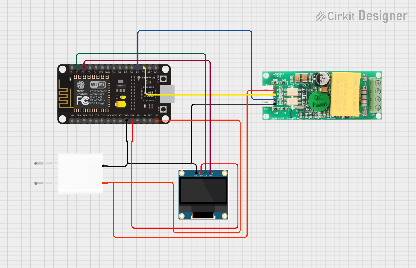
Connecting the PZEM-004T to an Arduino UNO

To use the PZEM-004T with an Arduino UNO, follow these steps:

  1. Power the Module: Connect the VCC pin of the PZEM-004T to the 5V pin of the Arduino UNO and the GND pin to the Arduino's GND.
  2. UART Communication: Connect the TX pin of the PZEM-004T to the RX pin of the Arduino UNO and the RX pin of the PZEM-004T to the TX pin of the Arduino UNO.
  3. AC Connections: Connect the AC IN+ and AC IN- terminals to the live and neutral wires of the AC circuit you want to monitor. Use the included current transformer (CT) to measure current by clamping it around the live wire.

Sample Arduino Code

Below is an example Arduino sketch to read data from the PZEM-004T module using the SoftwareSerial library:

#include <SoftwareSerial.h>

// Define RX and TX pins for SoftwareSerial
SoftwareSerial pzemSerial(10, 11); // RX = pin 10, TX = pin 11

// PZEM-004T communication commands
byte readCommand[] = {0xB0, 0xC0, 0xA8, 0x01, 0x01, 0x00, 0x1A}; // Example command

void setup() {
  Serial.begin(9600); // Initialize Serial Monitor
  pzemSerial.begin(9600); // Initialize PZEM-004T communication

  Serial.println("PZEM-004T Power Meter Example");
}

void loop() {
  // Send read command to PZEM-004T
  pzemSerial.write(readCommand, sizeof(readCommand));

  // Wait for response
  delay(100);

  // Check if data is available
  if (pzemSerial.available()) {
    Serial.println("Data received:");
    while (pzemSerial.available()) {
      byte data = pzemSerial.read();
      Serial.print(data, HEX); // Print data in hexadecimal format
      Serial.print(" ");
    }
    Serial.println();
  } else {
    Serial.println("No data received.");
  }

  delay(1000); // Wait 1 second before next read
}

Important Considerations

  • Safety First: Always handle AC connections with care. Ensure the circuit is powered off before making connections.
  • Current Transformer (CT): Ensure the CT is properly clamped around the live wire for accurate current measurement.
  • Baud Rate: The PZEM-004T communicates at a fixed baud rate of 9600. Ensure your microcontroller is configured accordingly.
  • Power Supply: The module requires a stable 5V DC power supply. Avoid using noisy power sources.

Troubleshooting and FAQs

Common Issues and Solutions

  1. No Data Received

    • Ensure the TX and RX pins are correctly connected (crossed: TX to RX and RX to TX).
    • Verify the baud rate is set to 9600 in your code.
    • Check the power supply to the PZEM-004T module.
  2. Incorrect Measurements

    • Ensure the AC IN+ and AC IN- terminals are connected to the correct live and neutral wires.
    • Verify the current transformer is properly clamped around the live wire.
  3. Module Not Responding

    • Check for loose connections in the UART interface.
    • Ensure the module is powered with a stable 5V DC supply.

FAQs

Q: Can the PZEM-004T measure DC circuits?
A: No, the PZEM-004T is designed specifically for AC circuits and cannot measure DC voltage or current.

Q: What is the maximum current the module can measure?
A: The module can measure up to 100A using the included current transformer.

Q: Can I use multiple PZEM-004T modules with a single Arduino?
A: Yes, you can use multiple modules by assigning unique addresses to each module and using a software or hardware UART multiplexer.

Q: Is the module safe for high-voltage applications?
A: The PZEM-004T is designed for 80V-260V AC circuits. Always follow proper safety precautions when working with high voltages.

This concludes the documentation for the PZEM-004T module. For further assistance, refer to the manufacturer's datasheet or community forums.