How to Use current_sensor: Examples, Pinouts, and Specs
Introduction
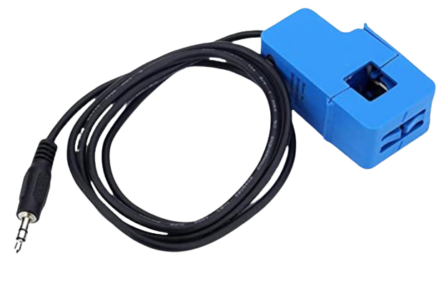
A current sensor is an electronic component that detects and measures the electric current flowing through a circuit. The output of the sensor is typically a voltage or digital signal proportional to the current being measured. Current sensors are widely used in various applications such as power supply monitoring, battery management, overcurrent protection, and energy metering.
Explore Projects Built with current_sensor
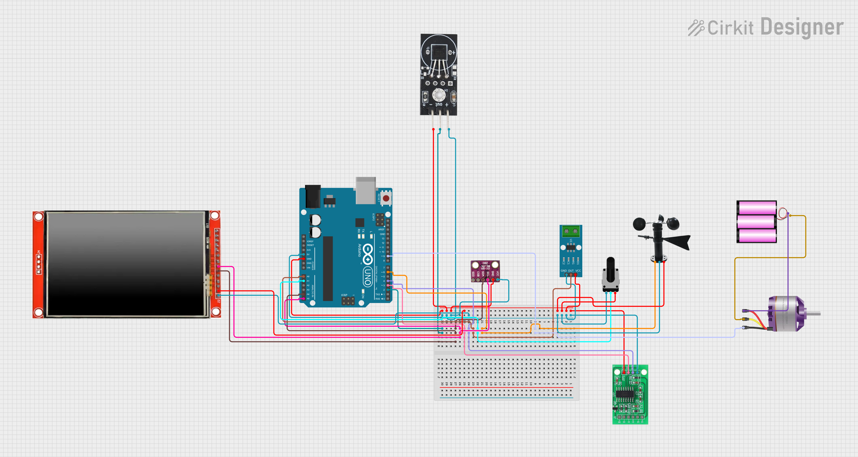


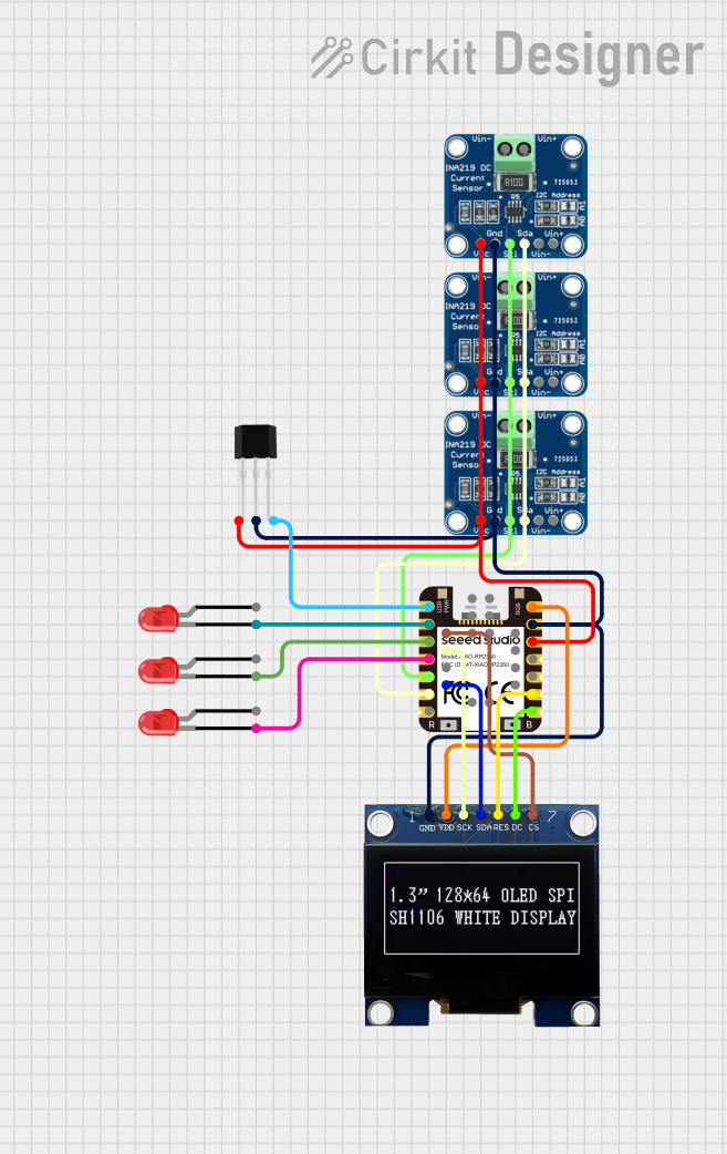
Explore Projects Built with current_sensor
Technical Specifications
Key Technical Details
- Measurement Range: Specifies the minimum and maximum current the sensor can measure.
- Sensitivity: The output voltage per unit of current measured (e.g., mV/A).
- Supply Voltage: The voltage required to power the sensor.
- Output Type: Analog (voltage) or digital (e.g., PWM, I2C, SPI).
- Accuracy: The degree to which the sensor's measurements are close to the actual current.
- Linearity: The extent to which the sensor's output is directly proportional to the current.
- Response Time: The time the sensor takes to respond to a change in current.
Pin Configuration and Descriptions
| Pin Number | Name | Description |
|---|---|---|
| 1 | Vcc | Power supply input, typically +5V or +3.3V |
| 2 | GND | Ground connection |
| 3 | OUT | Output signal (analog or digital) |
| 4 | NC | No connection (if applicable) |
Usage Instructions
How to Use the Component in a Circuit
Powering the Sensor: Connect the Vcc pin to a power source matching the sensor's supply voltage rating, and connect the GND pin to the system ground.
Reading the Output: Connect the OUT pin to an analog input of a microcontroller to read the analog voltage output. For digital output sensors, connect to the appropriate digital or communication pins.
Calibration: If necessary, calibrate the sensor using a known current source to ensure accurate readings.
Important Considerations and Best Practices
- Overcurrent Protection: Ensure the current does not exceed the sensor's maximum rating to prevent damage.
- Electrical Isolation: Some sensors provide galvanic isolation to protect the electronics from high voltages in the measured circuit.
- Noise Reduction: Use proper filtering and shielding techniques to minimize electrical noise that can affect accuracy.
- Temperature Effects: Be aware of the sensor's temperature coefficient and compensate for temperature variations if necessary.
Example Code for Arduino UNO
// Example code for interfacing a current sensor with an Arduino UNO
const int currentSensorPin = A0; // Analog input pin connected to the sensor

void setup() {
  Serial.begin(9600); // Start serial communication at 9600 baud rate
}

void loop() {
  int sensorValue = analogRead(currentSensorPin); // Read the sensor output
  float current = sensorValue * (5.0 / 1023.0); // Convert to current value
  Serial.println(current); // Print the current reading to the serial monitor
  delay(1000); // Wait for 1 second before reading again
}
Troubleshooting and FAQs
Common Issues
- Inaccurate Readings: Ensure the sensor is correctly calibrated and that there are no sources of electrical noise affecting the signal.
- No Output Signal: Check the power supply connections and verify that the sensor is not damaged.
- Intermittent Signal: Inspect the wiring for loose connections and ensure the sensor is not subjected to mechanical vibrations.
Solutions and Tips for Troubleshooting
- Calibration: Recalibrate the sensor periodically to maintain accuracy.
- Shielding: Use shielded cables for the sensor output to reduce noise.
- Power Supply: Use a stable and clean power source to prevent fluctuations that can affect the sensor's performance.
FAQs
Q: Can I use this sensor to measure AC current? A: It depends on the sensor model. Some current sensors are designed for AC measurements, while others are for DC only. Check the datasheet for your specific sensor.
Q: What is the maximum current I can measure with this sensor? A: The maximum measurable current is determined by the sensor's specifications. Exceeding this value can damage the sensor.
Q: How do I convert the sensor's output to actual current units? A: Use the sensor's sensitivity rating to convert the output voltage to current. For example, if the sensitivity is 100 mV/A, a 1V output corresponds to 10A.
Q: How often should I calibrate the sensor? A: Calibration frequency depends on the sensor's stability and the precision required for your application. Regular calibration is recommended for critical measurements.