Cirkit Designer Logo
Cirkit Designer
Your all-in-one circuit design IDE
Home / 
Component Documentation

How to Use 8-Channel AC 220V Optocoupler Input Module: Examples, Pinouts, and Specs

Image of 8-Channel AC 220V Optocoupler Input Module
Cirkit Designer LogoDesign with 8-Channel AC 220V Optocoupler Input Module in Cirkit Designer

Introduction

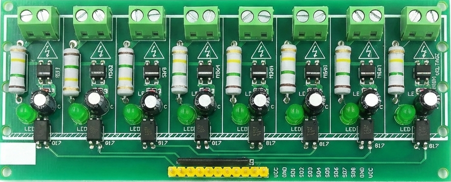
The 8-Channel AC 220V Optocoupler Input Module by Hailege is designed to safely interface high-voltage AC signals (up to 220V) with low-voltage control systems such as microcontrollers. This module uses optocouplers to provide electrical isolation, ensuring that high-voltage circuits do not directly interact with sensitive low-voltage components. It is ideal for applications requiring signal monitoring, industrial automation, and AC signal detection.

Explore Projects Built with 8-Channel AC 220V Optocoupler Input Module

Use Cirkit Designer to design, explore, and prototype these projects online. Some projects support real-time simulation. Click "Open Project" to start designing instantly!
ESP32-Based Wi-Fi Controlled 24V Input/Output Interface Module
Image of ESP32 4 på rad: A project utilizing 8-Channel AC 220V Optocoupler Input Module in a practical application
This circuit uses an ESP32 microcontroller to interface with a 3.3V PNP to 24V NPN photoelectric isolation module, which in turn connects to a 40-pin connector for general-purpose input and output. The 24V power supply provides the necessary voltage for the isolation module and the 40-pin connector, enabling the ESP32 to control and monitor high-voltage signals safely.
Cirkit Designer LogoOpen Project in Cirkit Designer
ESP32-Based Smart Power Monitoring and Control System with OLED Display
Image of Sistem monitoring terminal listrik rumah tangga: A project utilizing 8-Channel AC 220V Optocoupler Input Module in a practical application
This circuit is designed to monitor and control a 120V AC outlet using an ESP32 microcontroller. It includes a PZEM004t module for measuring voltage, current, and power, and a 12V relay to switch the outlet on and off. An OLED display is used to show real-time data, and the HLK-PM12 module provides the necessary 5V and 3.3V power to the components.
Cirkit Designer LogoOpen Project in Cirkit Designer
Cellular-Connected ESP32-CAM with Real-Time Clock and Isolated Control
Image of LRCM PHASE 2 PRO: A project utilizing 8-Channel AC 220V Optocoupler Input Module in a practical application
This circuit integrates a LilyGo-SIM7000G module with an RTC DS3231 for timekeeping, interfaced via I2C (SCL and SDA lines). An 8-Channel OPTO-COUPLER is used to isolate and interface external signals with the LilyGo-SIM7000G's GPIOs. Power is managed by a Buck converter, which steps down voltage from a DC Power Source to supply the ESP32-CAM and LilyGo-SIM7000G modules, as well as the OPTO-COUPLER.
Cirkit Designer LogoOpen Project in Cirkit Designer
Arduino Nano Controlled Octocoupler Interface for Signal Isolation
Image of complete togba no lcd: A project utilizing 8-Channel AC 220V Optocoupler Input Module in a practical application
This circuit uses optocouplers paired with 220-ohm resistors to interface an Arduino Nano with an external device via a 5-pin relimate connector, providing electrical isolation and signal transfer while protecting the microcontroller. The Arduino's digital I/O pins are connected to the optocouplers, but the control logic is not yet defined in the provided code.
Cirkit Designer LogoOpen Project in Cirkit Designer

Explore Projects Built with 8-Channel AC 220V Optocoupler Input Module

Use Cirkit Designer to design, explore, and prototype these projects online. Some projects support real-time simulation. Click "Open Project" to start designing instantly!
Image of ESP32 4 på rad: A project utilizing 8-Channel AC 220V Optocoupler Input Module in a practical application
ESP32-Based Wi-Fi Controlled 24V Input/Output Interface Module
This circuit uses an ESP32 microcontroller to interface with a 3.3V PNP to 24V NPN photoelectric isolation module, which in turn connects to a 40-pin connector for general-purpose input and output. The 24V power supply provides the necessary voltage for the isolation module and the 40-pin connector, enabling the ESP32 to control and monitor high-voltage signals safely.
Cirkit Designer LogoOpen Project in Cirkit Designer
Image of Sistem monitoring terminal listrik rumah tangga: A project utilizing 8-Channel AC 220V Optocoupler Input Module in a practical application
ESP32-Based Smart Power Monitoring and Control System with OLED Display
This circuit is designed to monitor and control a 120V AC outlet using an ESP32 microcontroller. It includes a PZEM004t module for measuring voltage, current, and power, and a 12V relay to switch the outlet on and off. An OLED display is used to show real-time data, and the HLK-PM12 module provides the necessary 5V and 3.3V power to the components.
Cirkit Designer LogoOpen Project in Cirkit Designer
Image of LRCM PHASE 2 PRO: A project utilizing 8-Channel AC 220V Optocoupler Input Module in a practical application
Cellular-Connected ESP32-CAM with Real-Time Clock and Isolated Control
This circuit integrates a LilyGo-SIM7000G module with an RTC DS3231 for timekeeping, interfaced via I2C (SCL and SDA lines). An 8-Channel OPTO-COUPLER is used to isolate and interface external signals with the LilyGo-SIM7000G's GPIOs. Power is managed by a Buck converter, which steps down voltage from a DC Power Source to supply the ESP32-CAM and LilyGo-SIM7000G modules, as well as the OPTO-COUPLER.
Cirkit Designer LogoOpen Project in Cirkit Designer
Image of complete togba no lcd: A project utilizing 8-Channel AC 220V Optocoupler Input Module in a practical application
Arduino Nano Controlled Octocoupler Interface for Signal Isolation
This circuit uses optocouplers paired with 220-ohm resistors to interface an Arduino Nano with an external device via a 5-pin relimate connector, providing electrical isolation and signal transfer while protecting the microcontroller. The Arduino's digital I/O pins are connected to the optocouplers, but the control logic is not yet defined in the provided code.
Cirkit Designer LogoOpen Project in Cirkit Designer

Common Applications and Use Cases

  • Industrial automation systems
  • AC signal monitoring and detection
  • Electrical safety isolation in control systems
  • Home automation projects
  • Interfacing high-voltage AC devices with microcontrollers (e.g., Arduino, Raspberry Pi)

Technical Specifications

The following table outlines the key technical details of the module:

Parameter Specification
Operating Voltage 220V AC
Number of Channels 8
Isolation Method Optocoupler
Output Voltage (Logic) 3.3V or 5V (compatible with most MCUs)
Output Type Digital (High/Low)
Input Signal Frequency 50Hz to 60Hz
PCB Dimensions 135mm x 55mm x 20mm
Mounting Holes 4 holes (M3 screws)

Pin Configuration and Descriptions

The module has two main interfaces: the AC input terminals and the low-voltage output pins. Below is the pin configuration:

AC Input Terminals

Terminal Description
IN1 to IN8 AC input channels for 220V signals (1 per channel)
COM Common terminal for AC input

Low-Voltage Output Pins

Pin Description
VCC Power supply for the module (3.3V or 5V)
GND Ground connection
OUT1 to OUT8 Digital outputs corresponding to IN1 to IN8

Usage Instructions

How to Use the Component in a Circuit

  1. Power the Module: Connect the VCC and GND pins to a 3.3V or 5V power source, depending on your microcontroller's logic level.
  2. Connect AC Signals: Attach the AC signals (up to 220V) to the input terminals (IN1 to IN8). Ensure proper wiring and insulation to avoid electrical hazards.
  3. Connect Outputs to Microcontroller: Connect the OUT1 to OUT8 pins to the digital input pins of your microcontroller. These pins will output a HIGH or LOW signal based on the presence of an AC signal on the corresponding input channel.
  4. Verify Connections: Double-check all connections to ensure safety and proper operation.

Important Considerations and Best Practices

  • Safety First: Always handle the module with care when working with high-voltage AC signals. Ensure proper insulation and avoid touching live wires.
  • Power Supply: Use a stable 3.3V or 5V power source for the module.
  • Signal Frequency: The module is designed for standard AC frequencies (50Hz to 60Hz). It may not work correctly with non-standard frequencies.
  • Output Logic: The output pins will typically output a LOW signal when an AC signal is detected and a HIGH signal when no AC signal is present. Verify this behavior with your specific module.

Example: Connecting to an Arduino UNO

Below is an example of how to connect the module to an Arduino UNO and read the status of the AC inputs:

Circuit Connections

  • Connect the module's VCC to the Arduino's 5V pin.
  • Connect the module's GND to the Arduino's GND pin.
  • Connect the module's OUT1 to Arduino digital pin 2, OUT2 to digital pin 3, and so on.

Arduino Code

// Define the input pins for the module
const int inputPins[] = {2, 3, 4, 5, 6, 7, 8, 9}; // OUT1 to OUT8

void setup() {
  // Initialize serial communication for debugging
  Serial.begin(9600);

  // Set the input pins as INPUT
  for (int i = 0; i < 8; i++) {
    pinMode(inputPins[i], INPUT);
  }
}

void loop() {
  // Read and print the status of each channel
  for (int i = 0; i < 8; i++) {
    int status = digitalRead(inputPins[i]);
    Serial.print("Channel ");
    Serial.print(i + 1);
    Serial.print(": ");
    Serial.println(status == LOW ? "AC Signal Detected" : "No Signal");
  }

  // Add a small delay to avoid flooding the serial monitor
  delay(500);
}

Troubleshooting and FAQs

Common Issues and Solutions

  1. No Output Signal Detected

    • Cause: Incorrect wiring or insufficient power supply.
    • Solution: Verify that the VCC and GND pins are properly connected and that the module is receiving the correct voltage.
  2. Output Always HIGH or LOW

    • Cause: Faulty AC input connection or damaged optocoupler.
    • Solution: Check the AC input wiring and ensure the input voltage is within the specified range. Replace the module if necessary.
  3. Microcontroller Not Detecting Output

    • Cause: Logic level mismatch or incorrect pin configuration.
    • Solution: Ensure the microcontroller's input pins are configured correctly and that the module's output logic level matches the microcontroller's requirements.

FAQs

Q: Can this module handle DC signals?
A: No, this module is designed specifically for AC signals. It will not work correctly with DC inputs.

Q: Is the module compatible with 3.3V microcontrollers like ESP32?
A: Yes, the module's output is compatible with both 3.3V and 5V logic levels.

Q: Can I use fewer than 8 channels?
A: Yes, you can use as many channels as needed. Unused channels can be left unconnected.

Q: What happens if the input voltage exceeds 220V AC?
A: Exceeding the rated voltage may damage the module and pose a safety hazard. Always ensure the input voltage is within the specified range.