
How to Use Adafruit AS7343 14 Channel Light Color Sensor Breakout: Examples, Pinouts, and Specs
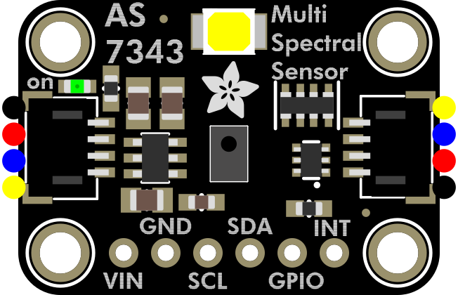
 Design with Adafruit AS7343 14 Channel Light Color Sensor Breakout in Cirkit Designer
Introduction
The Adafruit AS7343 14 Channel Light Color Sensor Breakout (Manufacturer Part ID: 6477) is a highly versatile sensor module designed to detect and measure light intensity across 14 distinct color channels. This advanced sensor enables precise color analysis, making it ideal for applications such as environmental monitoring, color matching, and scientific research. Its compact breakout board design ensures easy integration into a variety of projects.
Explore Projects Built with Adafruit AS7343 14 Channel Light Color Sensor Breakout
 Open Project in Cirkit Designer
 Open Project in Cirkit Designer
 Open Project in Cirkit Designer
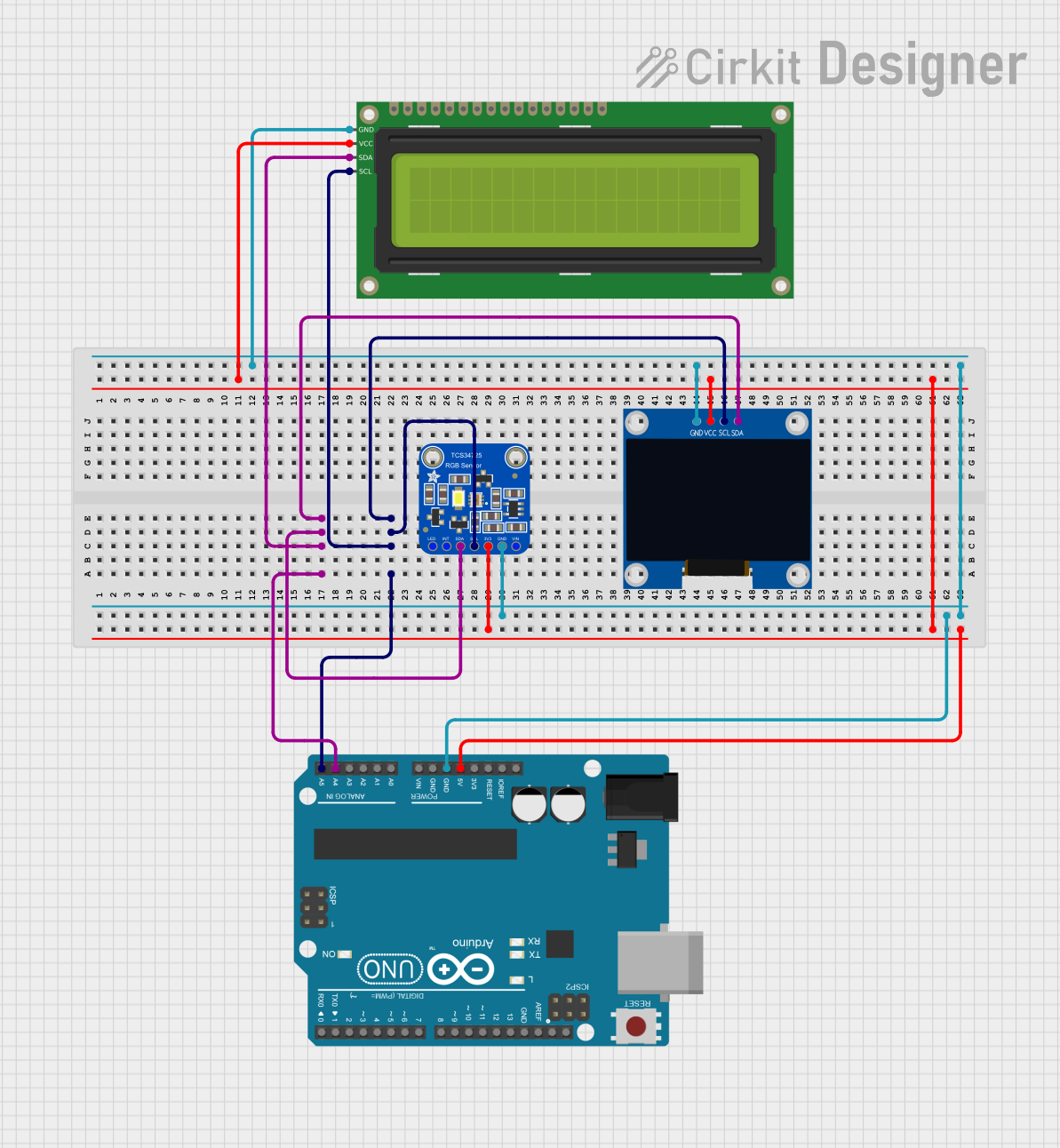 Open Project in Cirkit Designer
Explore Projects Built with Adafruit AS7343 14 Channel Light Color Sensor Breakout
Open Project in Cirkit DesignerOpen Project in Cirkit DesignerOpen Project in Cirkit DesignerOpen Project in Cirkit DesignerCommon Applications and Use Cases
- Environmental Monitoring: Measure ambient light and analyze spectral data for weather or agricultural applications.
- Color Matching: Used in industrial or artistic applications to ensure accurate color reproduction.
- Scientific Research: Analyze light spectra for experiments in physics, chemistry, or biology.
- Consumer Electronics: Enhance display calibration or lighting systems with precise color sensing.
Technical Specifications
The following table outlines the key technical details of the Adafruit AS7343 sensor:
| Parameter | Value |
|---|---|
| Operating Voltage | 3.3V to 5V |
| Communication Interface | I²C (default address: 0x39) |
| Spectral Channels | 14 (including UV, visible, and near-IR) |
| Spectral Range | 350 nm to 1000 nm |
| Measurement Resolution | 16-bit ADC |
| Operating Temperature | -40°C to +85°C |
| Dimensions | 25.4mm x 17.8mm x 4.6mm |
Pin Configuration and Descriptions
The breakout board features the following pins for easy connection:
| Pin | Name | Description |
|---|---|---|
| 1 | VIN | Power input (3.3V to 5V) |
| 2 | GND | Ground connection |
| 3 | SCL | I²C clock line |
| 4 | SDA | I²C data line |
| 5 | INT | Interrupt pin (optional, for event-driven applications) |
| 6 | RST | Reset pin (optional, to reset the sensor) |
Usage Instructions
How to Use the Component in a Circuit
- Power the Sensor: Connect the
VINpin to a 3.3V or 5V power source and theGNDpin to ground. - Connect I²C Lines: Attach the
SCLandSDApins to the corresponding I²C pins on your microcontroller (e.g., Arduino UNO). - Optional Connections: Use the
INTpin for interrupt-driven applications or theRSTpin to reset the sensor if needed. - Install Required Libraries: Download and install the Adafruit AS7343 library from the Arduino Library Manager.
- Write Code: Use the provided library functions to initialize the sensor, configure settings, and read spectral data.
Important Considerations and Best Practices
- I²C Pull-Up Resistors: Ensure that your I²C bus has appropriate pull-up resistors (typically 4.7kΩ) if not already present on your microcontroller.
- Power Supply: Use a stable power source to avoid noise in the spectral readings.
- Avoid Direct Sunlight: For accurate measurements, avoid exposing the sensor to direct sunlight, which may saturate the readings.
- Calibration: Perform calibration if precise spectral measurements are required for your application.
Example Code for Arduino UNO
Below is an example code snippet to get started with the Adafruit AS7343 sensor:
#include <Wire.h>
#include <Adafruit_AS7343.h>

// Create an instance of the AS7343 sensor
Adafruit_AS7343 as7343;

void setup() {
  Serial.begin(115200); // Initialize serial communication for debugging
  while (!Serial) delay(10); // Wait for Serial to initialize

  // Initialize I²C communication and the sensor
  if (!as7343.begin()) {
    Serial.println("Failed to find AS7343 sensor! Check connections.");
    while (1) delay(10); // Halt execution if sensor is not found
  }
  Serial.println("AS7343 sensor initialized successfully!");

  // Configure the sensor (e.g., set gain and measurement mode)
  as7343.setATIME(100); // Set integration time
  as7343.setASTEP(999); // Set step size
  as7343.setGain(AS7343_GAIN_256X); // Set gain to 256x
}

void loop() {
  // Read all 14 spectral channels
  uint16_t channels[14];
  if (as7343.readAllChannels(channels)) {
    Serial.println("Spectral Data:");
    for (int i = 0; i < 14; i++) {
      Serial.print("Channel ");
      Serial.print(i);
      Serial.print(": ");
      Serial.println(channels[i]);
    }
  } else {
    Serial.println("Failed to read spectral data.");
  }

  delay(1000); // Wait 1 second before the next reading
}
Troubleshooting and FAQs
Common Issues Users Might Face
Sensor Not Detected:
- Cause: Incorrect I²C wiring or address mismatch.
- Solution: Verify the
SCLandSDAconnections and ensure the I²C address is set to0x39.
Inaccurate Readings:
- Cause: Electrical noise or improper calibration.
- Solution: Use a stable power source and perform calibration if necessary.
Interrupt Pin Not Working:
- Cause: Interrupt pin not configured in the code.
- Solution: Ensure the
INTpin is connected and properly configured in your code.
Library Installation Issues:
- Cause: Missing or outdated Adafruit AS7343 library.
- Solution: Install or update the library via the Arduino Library Manager.
Solutions and Tips for Troubleshooting
- Check Connections: Double-check all wiring and ensure there are no loose connections.
- Use Serial Debugging: Print debug messages to the Serial Monitor to identify issues.
- Consult the Datasheet: Refer to the AS7343 datasheet for advanced configuration options and troubleshooting.
By following this documentation, you can effectively integrate the Adafruit AS7343 14 Channel Light Color Sensor Breakout into your projects and achieve precise color and light intensity measurements.