Cirkit Designer Logo
Cirkit Designer
Your all-in-one circuit design IDE
Home / 
Component Documentation

How to Use Adafruit Feather M0 RFM69: Examples, Pinouts, and Specs

Image of Adafruit Feather M0 RFM69
Cirkit Designer LogoDesign with Adafruit Feather M0 RFM69 in Cirkit Designer

Introduction

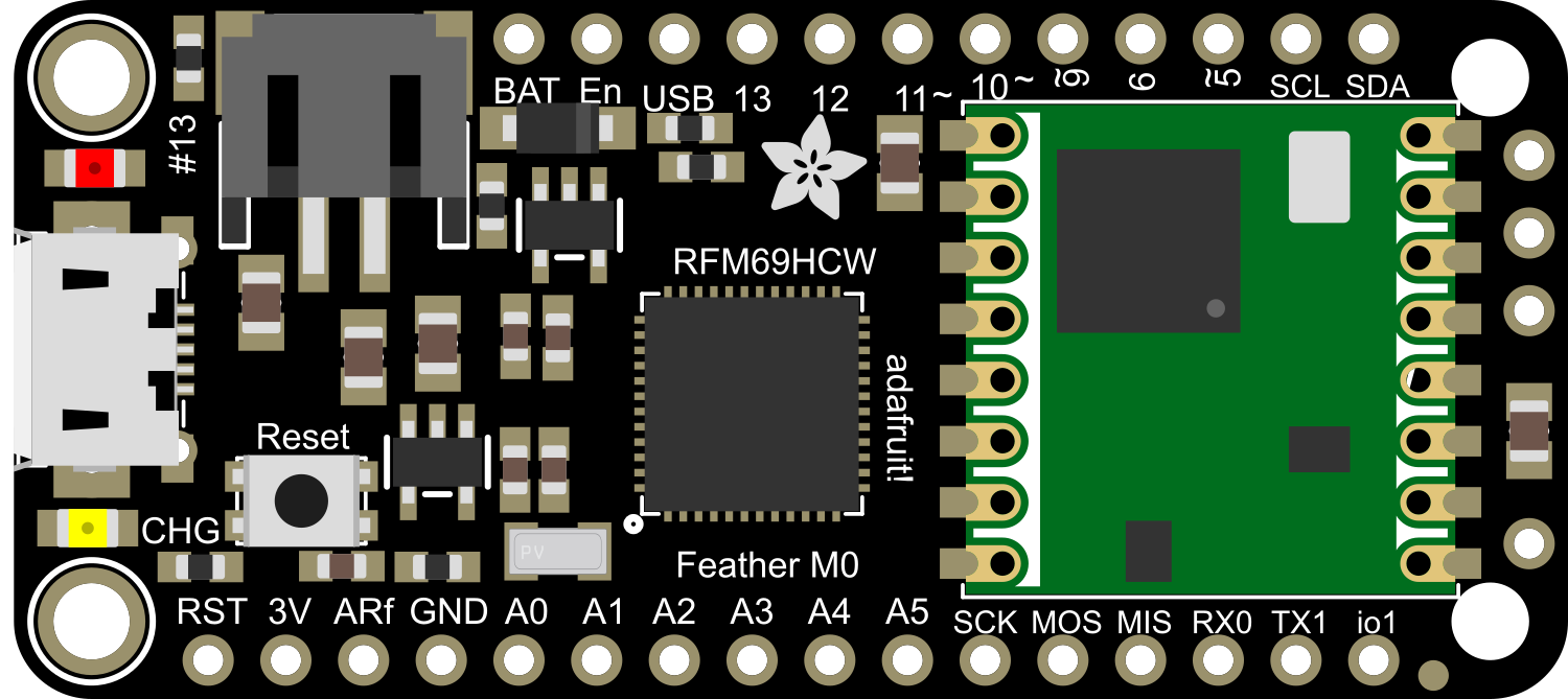
The Adafruit Feather M0 RFM69 is a versatile and powerful development board that combines the efficiency of the ATSAMD21G18 ARM Cortex M0 processor with the robust wireless communication capabilities of the RFM69HCW radio module. This board is part of the Feather ecosystem, designed by Adafruit to be compact, portable, and easy to integrate into various projects. It is particularly suitable for applications requiring long-range, low-power wireless communication, such as remote sensors, home automation, and IoT devices.

Explore Projects Built with Adafruit Feather M0 RFM69

Use Cirkit Designer to design, explore, and prototype these projects online. Some projects support real-time simulation. Click "Open Project" to start designing instantly!
Arduino MKR WiFi 1010 and Adafruit RFM9x LoRa Radio Communication System
Image of 1010: A project utilizing Adafruit Feather M0 RFM69 in a practical application
This circuit connects an Adafruit RFM9x LoRa Radio module to an Arduino MKR WiFi 1010 for wireless communication capabilities. The LoRa module's SPI interface (MOSI, MISO, SCK, CS) is connected to the corresponding SPI pins on the Arduino, allowing for serial data transfer between the devices. Additionally, the LoRa module's reset (RST) and interrupt (DIO0) pins are connected to digital pins on the Arduino for control and asynchronous communication.
Cirkit Designer LogoOpen Project in Cirkit Designer
Solar-Powered Environmental Data Logger with Adafruit Feather M0 Express
Image of Lake Thoreau Monitoring Station: A project utilizing Adafruit Feather M0 RFM69 in a practical application
This circuit is designed for environmental data collection and logging, utilizing an Adafruit Feather M0 Express microcontroller as the central processing unit. It interfaces with a BME280 sensor for atmospheric temperature, humidity, and pressure measurements, an SGP30 sensor for monitoring air quality (eCO2 and TVOC), and a STEMMA soil sensor for detecting soil moisture and temperature. The system is powered by a solar panel and a 3.7v LiPo battery, managed by an Adafruit BQ24074 Solar-DC-USB Lipo Charger, and provides easy access to the microcontroller's connections through an Adafruit Terminal Breakout FeatherWing.
Cirkit Designer LogoOpen Project in Cirkit Designer
Arduino Nano-Based GPS Tracker with GSM and LoRa Communication
Image of Electromagnetic Sensor: A project utilizing Adafruit Feather M0 RFM69 in a practical application
This circuit features an Arduino Nano microcontroller interfaced with an RFM95 LoRa transceiver module for long-range communication, a SIM800L GSM module for cellular connectivity, and a GPS NEO 6M module for location tracking. The Arduino Nano also connects to an inductive sensor for proximity or metal detection. The circuit is designed for applications requiring wireless communication, location tracking, and proximity sensing, with the Arduino Nano serving as the central processing unit.
Cirkit Designer LogoOpen Project in Cirkit Designer
Multi-Sensor Health Monitoring System with Adafruit Feather M0 Adalogger
Image of health tracker: A project utilizing Adafruit Feather M0 RFM69 in a practical application
This circuit is designed to interface multiple sensors with an Adafruit Feather M0 Adalogger microcontroller for data logging purposes. The sensors include a MAX30205 temperature sensor, a body dehydration sensor, a MAX30102 pulse oximeter, an Adafruit LSM6DSOX 6-axis accelerometer and gyroscope, and an Adafruit BME680 environmental sensor. All sensors are connected to the microcontroller via an I2C bus, sharing the SDA and SCL lines for communication.
Cirkit Designer LogoOpen Project in Cirkit Designer

Explore Projects Built with Adafruit Feather M0 RFM69

Use Cirkit Designer to design, explore, and prototype these projects online. Some projects support real-time simulation. Click "Open Project" to start designing instantly!
Image of 1010: A project utilizing Adafruit Feather M0 RFM69 in a practical application
Arduino MKR WiFi 1010 and Adafruit RFM9x LoRa Radio Communication System
This circuit connects an Adafruit RFM9x LoRa Radio module to an Arduino MKR WiFi 1010 for wireless communication capabilities. The LoRa module's SPI interface (MOSI, MISO, SCK, CS) is connected to the corresponding SPI pins on the Arduino, allowing for serial data transfer between the devices. Additionally, the LoRa module's reset (RST) and interrupt (DIO0) pins are connected to digital pins on the Arduino for control and asynchronous communication.
Cirkit Designer LogoOpen Project in Cirkit Designer
Image of Lake Thoreau Monitoring Station: A project utilizing Adafruit Feather M0 RFM69 in a practical application
Solar-Powered Environmental Data Logger with Adafruit Feather M0 Express
This circuit is designed for environmental data collection and logging, utilizing an Adafruit Feather M0 Express microcontroller as the central processing unit. It interfaces with a BME280 sensor for atmospheric temperature, humidity, and pressure measurements, an SGP30 sensor for monitoring air quality (eCO2 and TVOC), and a STEMMA soil sensor for detecting soil moisture and temperature. The system is powered by a solar panel and a 3.7v LiPo battery, managed by an Adafruit BQ24074 Solar-DC-USB Lipo Charger, and provides easy access to the microcontroller's connections through an Adafruit Terminal Breakout FeatherWing.
Cirkit Designer LogoOpen Project in Cirkit Designer
Image of Electromagnetic Sensor: A project utilizing Adafruit Feather M0 RFM69 in a practical application
Arduino Nano-Based GPS Tracker with GSM and LoRa Communication
This circuit features an Arduino Nano microcontroller interfaced with an RFM95 LoRa transceiver module for long-range communication, a SIM800L GSM module for cellular connectivity, and a GPS NEO 6M module for location tracking. The Arduino Nano also connects to an inductive sensor for proximity or metal detection. The circuit is designed for applications requiring wireless communication, location tracking, and proximity sensing, with the Arduino Nano serving as the central processing unit.
Cirkit Designer LogoOpen Project in Cirkit Designer
Image of health tracker: A project utilizing Adafruit Feather M0 RFM69 in a practical application
Multi-Sensor Health Monitoring System with Adafruit Feather M0 Adalogger
This circuit is designed to interface multiple sensors with an Adafruit Feather M0 Adalogger microcontroller for data logging purposes. The sensors include a MAX30205 temperature sensor, a body dehydration sensor, a MAX30102 pulse oximeter, an Adafruit LSM6DSOX 6-axis accelerometer and gyroscope, and an Adafruit BME680 environmental sensor. All sensors are connected to the microcontroller via an I2C bus, sharing the SDA and SCL lines for communication.
Cirkit Designer LogoOpen Project in Cirkit Designer

Technical Specifications

Processor:

  • Microcontroller: ATSAMD21G18 ARM Cortex M0
  • Clock Speed: 48 MHz
  • Flash Memory: 256 KB
  • SRAM: 32 KB

Radio Module:

  • Model: RFM69HCW
  • Frequency Bands: 315 MHz, 433 MHz, 868 MHz, or 915 MHz (region-specific)
  • Output Power: +13 to +20 dBm up to 100 mW Power Output Capability
  • Sensitivity: down to -120 dBm

Power:

  • Supply Voltage: 3.3V
  • Logic Level: 3.3V
  • Current: 120 mA peak during +20 dBm transmit, 30 mA during active radio listening.

Pin Configuration:

Pin Number Function Description
1 GND Ground
2 3V 3.3V Supply
3 AREF Analog reference voltage
4 A0-D8 Analog input 0 or Digital I/O pin 8
... ... ...
20 SCK Serial Clock for SPI communication
21 MISO Master In Slave Out for SPI communication
22 MOSI Master Out Slave In for SPI communication
23 RX UART Receive pin
24 TX UART Transmit pin

Note: This is a partial list. Refer to the official pinout diagram for complete details.

Usage Instructions

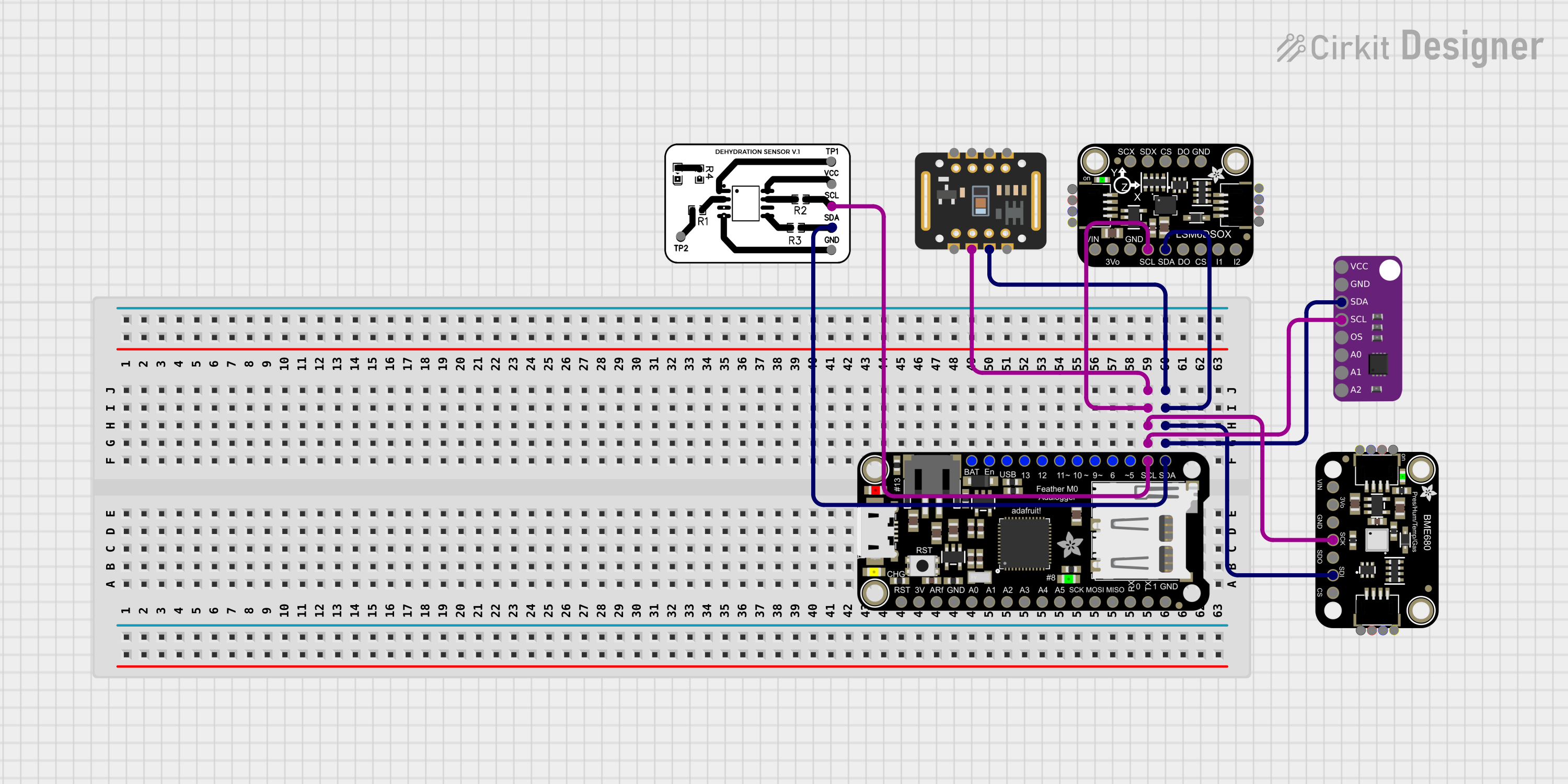
Integration into a Circuit:

  1. Powering the Board: Connect a 3.7V Lithium polymer battery to the JST connector for a portable power solution, or supply 3.3V through the 3V pin.
  2. Programming: Use the micro USB connection to program the board with the Arduino IDE or other compatible software.
  3. Radio Communication: Connect an antenna to the board's uFL connector to enable radio communication.

Best Practices:

  • Ensure that the power supply is clean and stable to prevent damage to the board.
  • Use a regulated 3.3V supply when not using a battery.
  • Always attach an appropriate antenna before powering up the radio module to avoid damage.
  • Follow the regional frequency regulations when setting up the radio communication.

Example Code for Arduino UNO

#include <SPI.h>
#include <RH_RF69.h>

// Singleton instance of the radio driver
RH_RF69 rf69;

void setup() 
{
  Serial.begin(9600);
  if (!rf69.init())
    Serial.println("RFM69 radio init failed");
  if (!rf69.setFrequency(915.0))
    Serial.println("setFrequency failed");
  
  // The encryption key has to be the same as the one in the server
  uint8_t key[] = { 0x01, 0x02, 0x03, 0x04, 0x05, 0x06, 0x07, 0x08,
                    0x09, 0x10, 0x11, 0x12, 0x13, 0x14, 0x15, 0x16 };
  rf69.setEncryptionKey(key);
}

void loop()
{
  // Send a message to the server every 5 seconds
  const char *msg = "Hello World!";
  rf69.send((uint8_t *)msg, strlen(msg));
  rf69.waitPacketSent();
  delay(5000);
}

Troubleshooting and FAQs

Common Issues:

  • Radio Not Initializing: Ensure the antenna is properly connected and the board is powered correctly.
  • Communication Failure: Check the frequency and encryption key match between devices.
  • Low Range: Verify the antenna type and orientation, and ensure there are no obstructions or interference.

FAQs:

Q: Can I use the Feather M0 RFM69 with a 5V system? A: No, the Feather M0 RFM69 operates at 3.3V. Using it with a 5V system without proper logic level conversion can damage the board.

Q: How do I choose the right antenna? A: The antenna should match the frequency band of your RFM69 module. For optimal performance, use a quarter-wave monopole or a dipole antenna.

Q: What is the maximum range of the RFM69 module? A: The range depends on many factors, including power output, antenna, and environmental conditions. Under ideal conditions, it can reach several hundred meters.

For further assistance, consult the Adafruit Feather M0 RFM69 forums and the extensive online community resources.