
How to Use FM Transmitter: Examples, Pinouts, and Specs
 Design with FM Transmitter in Cirkit Designer
Introduction
An FM transmitter is a device that generates frequency-modulated (FM) radio waves to transmit audio signals wirelessly over a specific frequency range. It is widely used for short-range broadcasting, such as transmitting audio from a smartphone or microphone to an FM radio receiver. FM transmitters are commonly employed in applications like personal audio broadcasting, wireless communication systems, and low-power radio stations.
Explore Projects Built with FM Transmitter
 Open Project in Cirkit Designer
 Open Project in Cirkit Designer
 Open Project in Cirkit Designer
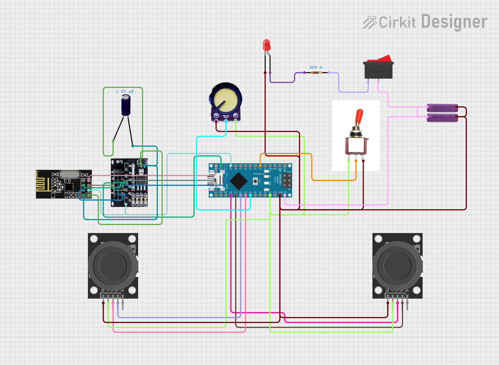 Open Project in Cirkit Designer
Explore Projects Built with FM Transmitter
Open Project in Cirkit DesignerOpen Project in Cirkit DesignerOpen Project in Cirkit DesignerOpen Project in Cirkit DesignerCommon Applications and Use Cases
- Wireless audio transmission to FM radios
- Personal broadcasting (e.g., in cars or homes)
- Assistive listening systems
- Educational or community radio stations
- Wireless microphone systems
Technical Specifications
Below are the general technical specifications for a typical FM transmitter. Note that specific models may vary slightly in their parameters.
| Parameter | Specification |
|---|---|
| Operating Voltage | 3V to 12V DC |
| Frequency Range | 88 MHz to 108 MHz |
| Modulation Type | Frequency Modulation (FM) |
| Transmission Range | Up to 100 meters (varies by power output) |
| Audio Input | 3.5mm jack or microphone input |
| Output Power | Typically 10mW to 500mW |
| Antenna Type | External wire or telescopic antenna |
Pin Configuration and Descriptions
The pin configuration for an FM transmitter module may vary depending on the model. Below is an example of a common FM transmitter module:
| Pin Name | Description |
|---|---|
| VCC | Power supply input (3V to 12V DC) |
| GND | Ground connection |
| AUDIO IN | Audio signal input (e.g., from a 3.5mm jack or mic) |
| ANT | Antenna connection for transmitting FM signals |
Usage Instructions
How to Use the FM Transmitter in a Circuit
- Power the Module: Connect the
VCCpin to a DC power source (3V to 12V) and theGNDpin to ground. - Connect the Audio Source: Use the
AUDIO INpin to connect an audio source, such as a smartphone, MP3 player, or microphone. For devices with a 3.5mm audio jack, use an appropriate cable. - Attach the Antenna: Connect a wire or telescopic antenna to the
ANTpin to ensure proper signal transmission. - Set the Frequency: Adjust the frequency of the FM transmitter (if adjustable) to match the desired FM band (e.g., 88 MHz to 108 MHz). This is typically done using a tuning knob or digital controls.
- Test the Transmission: Tune an FM radio receiver to the same frequency as the transmitter to verify the audio signal is being broadcast.
Important Considerations and Best Practices
- Antenna Placement: Ensure the antenna is properly connected and positioned for optimal signal strength and range.
- Avoid Interference: Choose a frequency that is not already in use by local FM radio stations to avoid interference.
- Power Supply: Use a stable power supply to prevent noise or distortion in the transmitted signal.
- Legal Compliance: Check local regulations regarding FM transmission power limits and frequency usage to ensure compliance.
Example: Connecting an FM Transmitter to an Arduino UNO
An FM transmitter can be used with an Arduino UNO to broadcast audio signals. Below is an example of how to send a simple tone signal using the Arduino's PWM output.
Circuit Connections
- Connect the
VCCandGNDpins of the FM transmitter to the Arduino's5VandGNDpins, respectively. - Connect the
AUDIO INpin of the FM transmitter to the Arduino's PWM output pin (e.g., pin 9). - Attach an antenna to the
ANTpin of the FM transmitter.
Arduino Code
// Simple Arduino code to generate a tone signal for an FM transmitter
// Connect the AUDIO IN pin of the FM transmitter to pin 9 of the Arduino

void setup() {
  pinMode(9, OUTPUT); // Set pin 9 as an output
}

void loop() {
  // Generate a 1 kHz tone signal on pin 9
  tone(9, 1000); // 1000 Hz frequency
  delay(1000);   // Transmit the tone for 1 second

  noTone(9);     // Stop the tone
  delay(1000);   // Wait for 1 second before repeating
}
Note: This example generates a simple tone signal. For transmitting actual audio, you would need to process the audio signal and feed it into the
AUDIO INpin.
Troubleshooting and FAQs
Common Issues and Solutions
No Signal Detected on FM Radio
- Ensure the FM transmitter and radio are tuned to the same frequency.
- Check the antenna connection and ensure it is properly positioned.
- Verify the power supply voltage is within the specified range.
Poor Audio Quality
- Use a stable power supply to minimize noise.
- Ensure the audio source is not overdriving the transmitter (reduce input volume if necessary).
- Adjust the antenna placement for better signal strength.
Short Transmission Range
- Check the antenna length and placement. A longer antenna may improve range.
- Ensure there are no obstructions between the transmitter and receiver.
Interference with Other FM Stations
- Select a frequency that is not already in use by local FM stations.
- Use a frequency scanner to identify free channels in your area.
FAQs
Q: Can I use the FM transmitter without an antenna?
A: While some FM transmitters may work without an antenna, the transmission range and signal quality will be significantly reduced. Always connect an antenna for optimal performance.
Q: Is it legal to use an FM transmitter?
A: The legality of using an FM transmitter depends on your location and the transmitter's power output. Check local regulations to ensure compliance.
Q: Can I transmit stereo audio with an FM transmitter?
A: Yes, many FM transmitters support stereo audio transmission. Ensure your transmitter is designed for stereo operation.
Q: How can I increase the transmission range?
A: Use a longer antenna, ensure a clear line of sight between the transmitter and receiver, and operate within the legal power limits for your region.