How to Use Color Sensor: Examples, Pinouts, and Specs
Introduction
The TCS3200, manufactured by ams OSRAM (formerly TAOS), is a programmable color light-to-frequency converter. It detects and measures the color of an object or light source by converting light intensity into a frequency signal. The sensor is equipped with an array of photodiodes and filters that allow it to sense red, green, blue, and clear light components.
This versatile component is widely used in applications such as:
- Robotics for color-based navigation or sorting
- Industrial automation for color detection and quality control
- Consumer electronics for color recognition
- Educational projects involving Arduino or other microcontrollers
Explore Projects Built with Color Sensor

Explore Projects Built with Color Sensor
Technical Specifications
The TCS3200 is a highly flexible and accurate color sensor. Below are its key technical details:
Key Specifications
| Parameter | Value |
|---|---|
| Supply Voltage (Vcc) | 2.7V to 5.5V |
| Operating Current | 2 mA (typical) |
| Output | Square wave (frequency proportional to light intensity) |
| Frequency Scaling | 100%, 20%, 2%, or Power Down |
| Photodiode Array | 8x8 (64 photodiodes) |
| Filters | Red, Green, Blue, and Clear |
| Operating Temperature | -40°C to +85°C |
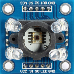
Pin Configuration and Descriptions
The TCS3200 is typically available in an 8-pin DIP or module form. Below is the pinout description:
TCS3200 Pinout Table
| Pin No. | Name | Description |
|---|---|---|
| 1 | S0 | Output frequency scaling selection input (see usage instructions) |
| 2 | S1 | Output frequency scaling selection input (see usage instructions) |
| 3 | OE | Output enable (active low, enables the output when pulled low) |
| 4 | GND | Ground (0V reference) |
| 5 | OUT | Output frequency signal (square wave proportional to light intensity) |
| 6 | Vcc | Supply voltage (2.7V to 5.5V) |
| 7 | S2 | Photodiode filter selection input (see usage instructions) |
| 8 | S3 | Photodiode filter selection input (see usage instructions) |
Usage Instructions
The TCS3200 is straightforward to use in a circuit. Below are the steps and considerations for integrating it into your project:
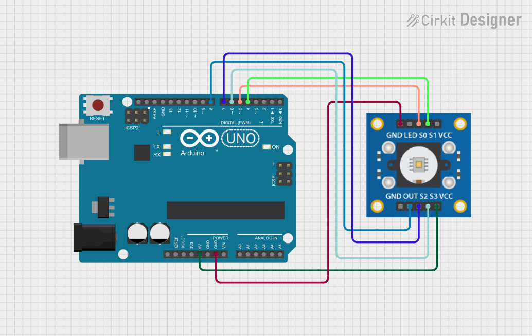
Connecting the TCS3200
- Power Supply: Connect the
Vccpin to a 3.3V or 5V power source and theGNDpin to ground. - Output Enable: Pull the
OEpin low to enable the output signal. - Frequency Scaling: Use the
S0andS1pins to set the output frequency scaling:S0 = LOW,S1 = LOW: Power down modeS0 = LOW,S1 = HIGH: 2% scalingS0 = HIGH,S1 = LOW: 20% scalingS0 = HIGH,S1 = HIGH: 100% scaling
- Filter Selection: Use the
S2andS3pins to select the photodiode filter:S2 = LOW,S3 = LOW: Red filterS2 = LOW,S3 = HIGH: Blue filterS2 = HIGH,S3 = LOW: Clear (no filter)S2 = HIGH,S3 = HIGH: Green filter
- Output Signal: Connect the
OUTpin to a microcontroller or frequency counter to read the output signal.
Example Arduino Code
Below is an example of how to use the TCS3200 with an Arduino UNO to detect colors:
// TCS3200 Color Sensor Example with Arduino UNO
// Connect TCS3200 pins: S0, S1, S2, S3, OUT, OE, Vcc, GND to Arduino

#define S0 2  // Connect to Arduino digital pin 2
#define S1 3  // Connect to Arduino digital pin 3
#define S2 4  // Connect to Arduino digital pin 4
#define S3 5  // Connect to Arduino digital pin 5
#define OUT 6 // Connect to Arduino digital pin 6
#define OE 7  // Connect to Arduino digital pin 7

void setup() {
  pinMode(S0, OUTPUT);
  pinMode(S1, OUTPUT);
  pinMode(S2, OUTPUT);
  pinMode(S3, OUTPUT);
  pinMode(OE, OUTPUT);
  pinMode(OUT, INPUT);

  // Set frequency scaling to 20%
  digitalWrite(S0, HIGH);
  digitalWrite(S1, LOW);

  // Enable the output
  digitalWrite(OE, LOW);

  Serial.begin(9600); // Initialize serial communication
}

void loop() {
  // Select Red filter
  digitalWrite(S2, LOW);
  digitalWrite(S3, LOW);
  int redFrequency = pulseIn(OUT, LOW); // Measure frequency for red light

  // Select Green filter
  digitalWrite(S2, HIGH);
  digitalWrite(S3, HIGH);
  int greenFrequency = pulseIn(OUT, LOW); // Measure frequency for green light

  // Select Blue filter
  digitalWrite(S2, LOW);
  digitalWrite(S3, HIGH);
  int blueFrequency = pulseIn(OUT, LOW); // Measure frequency for blue light

  // Print the measured frequencies
  Serial.print("Red: ");
  Serial.print(redFrequency);
  Serial.print(" Green: ");
  Serial.print(greenFrequency);
  Serial.print(" Blue: ");
  Serial.println(blueFrequency);

  delay(500); // Wait for 500ms before the next reading
}
Best Practices
- Use decoupling capacitors (e.g., 0.1 µF) near the power supply pins to reduce noise.
- Avoid exposing the sensor to direct sunlight or strong ambient light, as it may affect accuracy.
- Calibrate the sensor for your specific application to improve color detection accuracy.
Troubleshooting and FAQs
Common Issues
No Output Signal:
- Ensure the
OEpin is pulled low to enable the output. - Verify the power supply voltage is within the specified range (2.7V to 5.5V).
- Ensure the
Inaccurate Color Readings:
- Check the filter selection pins (
S2andS3) for proper configuration. - Ensure the sensor is not exposed to excessive ambient light.
- Check the filter selection pins (
Fluctuating Frequency Output:
- Use a stable power supply and add decoupling capacitors to reduce noise.
- Verify that the sensor is not being affected by vibrations or movement.
FAQs
Q: Can the TCS3200 detect black or white?
A: Yes, the TCS3200 can detect black and white. Black will result in a very low frequency output, while white will produce a high frequency output due to the reflection of all colors.
Q: How do I improve the accuracy of color detection?
A: Calibrate the sensor by measuring known color samples and adjusting your code to account for variations in frequency output.
Q: Can I use the TCS3200 with a 3.3V microcontroller?
A: Yes, the TCS3200 operates within a supply voltage range of 2.7V to 5.5V, making it compatible with 3.3V systems.
By following this documentation, you can effectively integrate the TCS3200 color sensor into your projects for accurate and reliable color detection.