How to Use ESP32S3: Examples, Pinouts, and Specs

 Design with ESP32S3 in Cirkit Designer
Introduction
The ESP32S3, manufactured by Goouuuu, is a powerful and versatile system on a chip (SoC) designed for Internet of Things (IoT) applications. It combines dual-core processing power with integrated Wi-Fi and Bluetooth capabilities, making it an excellent choice for smart devices, home automation, wearable electronics, and other wireless connectivity applications. The ESP32S3 is optimized for low power consumption, ensuring efficient operation in battery-powered devices.
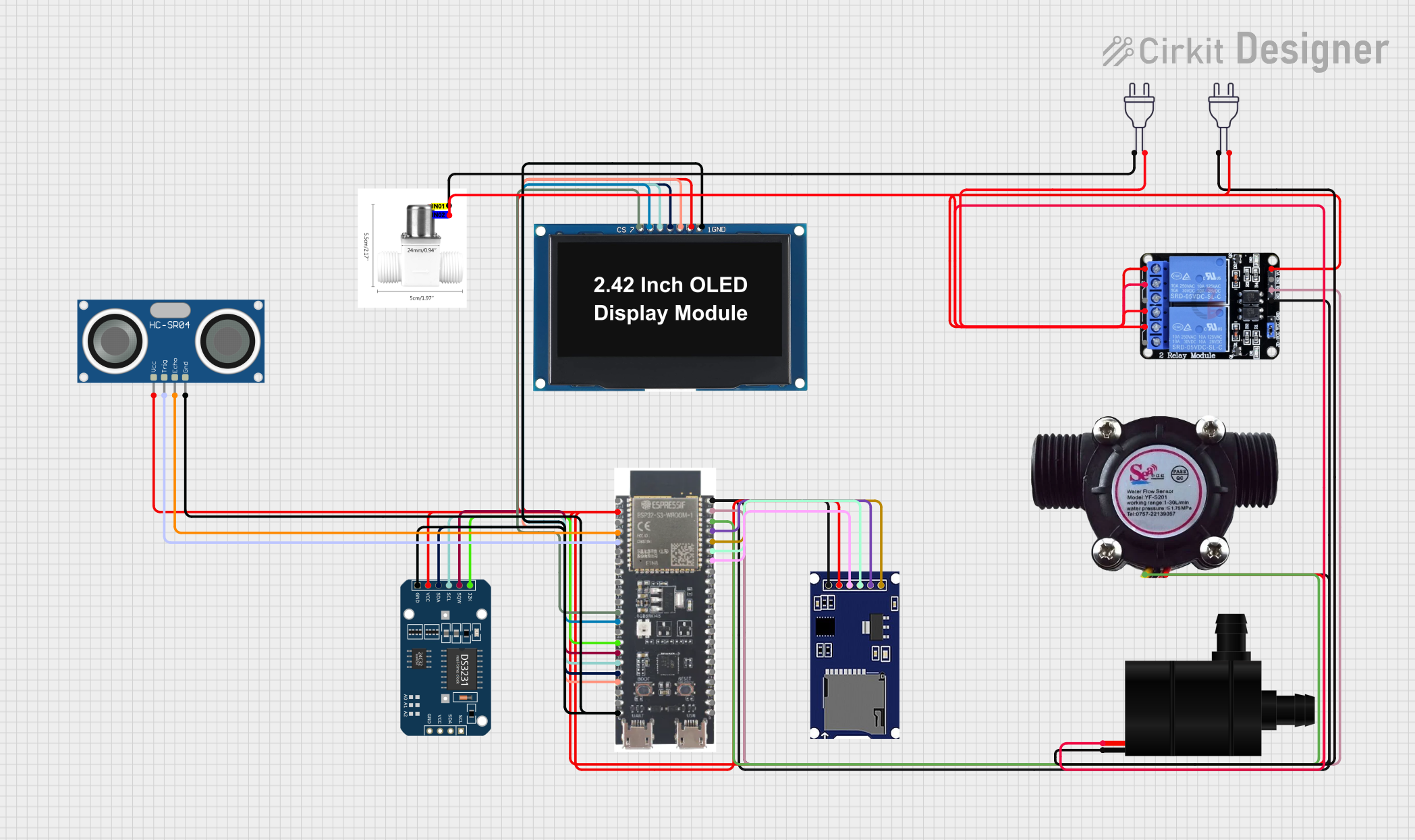
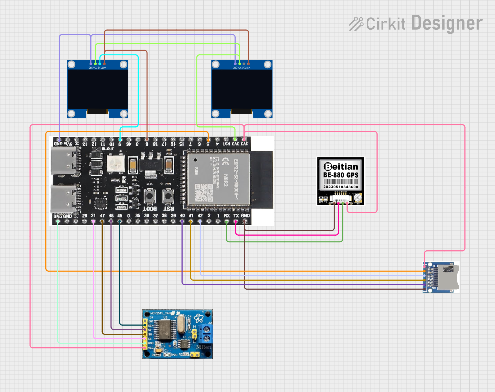
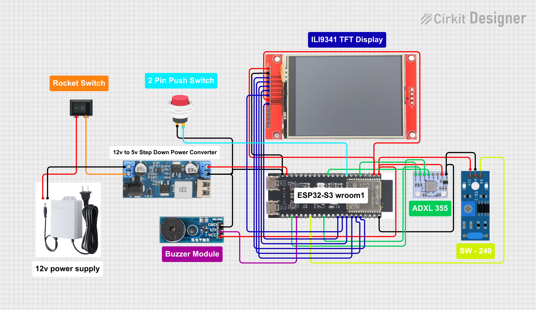
Explore Projects Built with ESP32S3

 Open Project in Cirkit Designer
 Open Project in Cirkit Designer
 Open Project in Cirkit Designer
 Open Project in Cirkit Designer
Explore Projects Built with ESP32S3

 Open Project in Cirkit Designer
 Open Project in Cirkit Designer
 Open Project in Cirkit Designer
 Open Project in Cirkit Designer
Common Applications
- Smart home devices (e.g., smart lights, thermostats)
- Wearable electronics
- Industrial IoT systems
- Wireless sensor networks
- Robotics and automation
- Audio streaming and voice recognition systems
Technical Specifications
The ESP32S3 offers a robust set of features and specifications, making it suitable for a wide range of applications.
Key Technical Details
| Specification | Value |
|---|---|
| Processor | Dual-core Xtensa® LX7 @ 240 MHz |
| Wireless Connectivity | Wi-Fi 802.11 b/g/n, Bluetooth 5.0 (LE) |
| Flash Memory | Up to 16 MB |
| SRAM | 512 KB |
| GPIO Pins | 45 (configurable for various peripherals) |
| Operating Voltage | 3.0V to 3.6V |
| Power Consumption (Idle) | ~10 µA |
| ADC Resolution | 12-bit |
| DAC Resolution | 8-bit |
| Communication Interfaces | UART, SPI, I2C, I2S, CAN, PWM |
| USB Support | USB OTG |
| Temperature Range | -40°C to 85°C |
Pin Configuration and Descriptions
The ESP32S3 has a flexible pinout, with many pins configurable for multiple functions. Below is a summary of the key pins:
| Pin Name | Function(s) | Description |
|---|---|---|
| GPIO0 | Input/Output, Boot Mode | Used for boot mode selection during startup. |
| GPIO1 | UART TX | Default UART transmit pin. |
| GPIO2 | Input/Output, ADC, PWM | General-purpose pin with ADC and PWM support. |
| GPIO3 | UART RX | Default UART receive pin. |
| GPIO4 | Input/Output, ADC, PWM | General-purpose pin with ADC and PWM support. |
| GPIO18 | SPI CLK | Clock pin for SPI communication. |
| GPIO19 | SPI MISO | Master In Slave Out for SPI communication. |
| GPIO23 | SPI MOSI | Master Out Slave In for SPI communication. |
| GPIO25 | DAC1, PWM | Digital-to-Analog Converter channel 1. |
| GPIO26 | DAC2, PWM | Digital-to-Analog Converter channel 2. |
| EN | Enable | Chip enable pin. Pull high to enable the chip. |
| 3V3 | Power | 3.3V power supply input. |
| GND | Ground | Ground connection. |
Note: Many GPIO pins are multiplexed and can be configured for different functions. Refer to the full datasheet for detailed pin mapping.
Usage Instructions
The ESP32S3 is highly versatile and can be used in a variety of circuits. Below are the steps and best practices for using the ESP32S3 in your projects.
Basic Circuit Setup
- Power Supply: Connect the 3V3 pin to a stable 3.3V power source and the GND pin to ground.
- Boot Mode: To upload code, connect GPIO0 to GND during reset to enter bootloader mode.
- Communication: Use the UART pins (GPIO1 for TX and GPIO3 for RX) to communicate with a computer or microcontroller.
- Peripherals: Connect sensors, actuators, or other devices to the GPIO pins. Configure the pins in your code for the desired function (e.g., ADC, PWM, I2C).
Example: Connecting to an Arduino UNO
The ESP32S3 can be programmed using the Arduino IDE. Below is an example of how to blink an LED connected to GPIO2.
Code Example
// Include the Arduino library for ESP32
#include <Arduino.h>

// Define the GPIO pin for the LED
#define LED_PIN 2

void setup() {
  // Set the LED pin as an output
  pinMode(LED_PIN, OUTPUT);
}

void loop() {
  // Turn the LED on
  digitalWrite(LED_PIN, HIGH);
  delay(1000); // Wait for 1 second

  // Turn the LED off
  digitalWrite(LED_PIN, LOW);
  delay(1000); // Wait for 1 second
}
Best Practices
- Use a stable power supply to avoid voltage fluctuations.
- Avoid exceeding the maximum current rating of GPIO pins (typically 12 mA per pin).
- Use pull-up or pull-down resistors for input pins to prevent floating states.
- When using Wi-Fi or Bluetooth, ensure proper antenna placement for optimal signal strength.
Troubleshooting and FAQs
Common Issues
ESP32S3 Not Responding
- Cause: Incorrect boot mode configuration.
- Solution: Ensure GPIO0 is connected to GND during reset for bootloader mode.
Wi-Fi Connection Fails
- Cause: Incorrect SSID or password.
- Solution: Double-check the Wi-Fi credentials in your code.
Overheating
- Cause: Excessive current draw or poor ventilation.
- Solution: Ensure proper heat dissipation and avoid overloading GPIO pins.
Code Upload Fails
- Cause: Incorrect COM port or baud rate.
- Solution: Verify the correct COM port is selected in the Arduino IDE and use a baud rate of 115200.
FAQs
Q: Can the ESP32S3 operate on 5V?
A: No, the ESP32S3 operates on 3.3V. Using 5V can damage the chip.
Q: How do I reset the ESP32S3?
A: Press the EN (Enable) button on the board to reset the chip.
Q: Can I use the ESP32S3 for audio applications?
A: Yes, the ESP32S3 supports I2S and has built-in DACs, making it suitable for audio processing.
Q: Is the ESP32S3 compatible with Arduino libraries?
A: Yes, the ESP32S3 is supported by the Arduino IDE and many libraries are compatible.
By following this documentation, you can effectively integrate the ESP32S3 into your projects and troubleshoot common issues. For advanced configurations, refer to the official datasheet and programming guides.