
How to Use Telemetria: Examples, Pinouts, and Specs
 Design with Telemetria in Cirkit Designer
Introduction
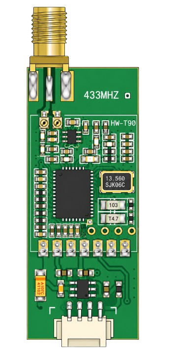
Telemetria refers to the technology and systems used for remote measurement and reporting of data. It enables the collection of data from sensors or devices located in remote or inaccessible areas and transmits this data to a central system for monitoring, analysis, and control. Telemetria is widely used in various industries, including environmental monitoring, industrial automation, healthcare, and transportation.
Explore Projects Built with Telemetria
 Open Project in Cirkit Designer
 Open Project in Cirkit Designer
 Open Project in Cirkit Designer
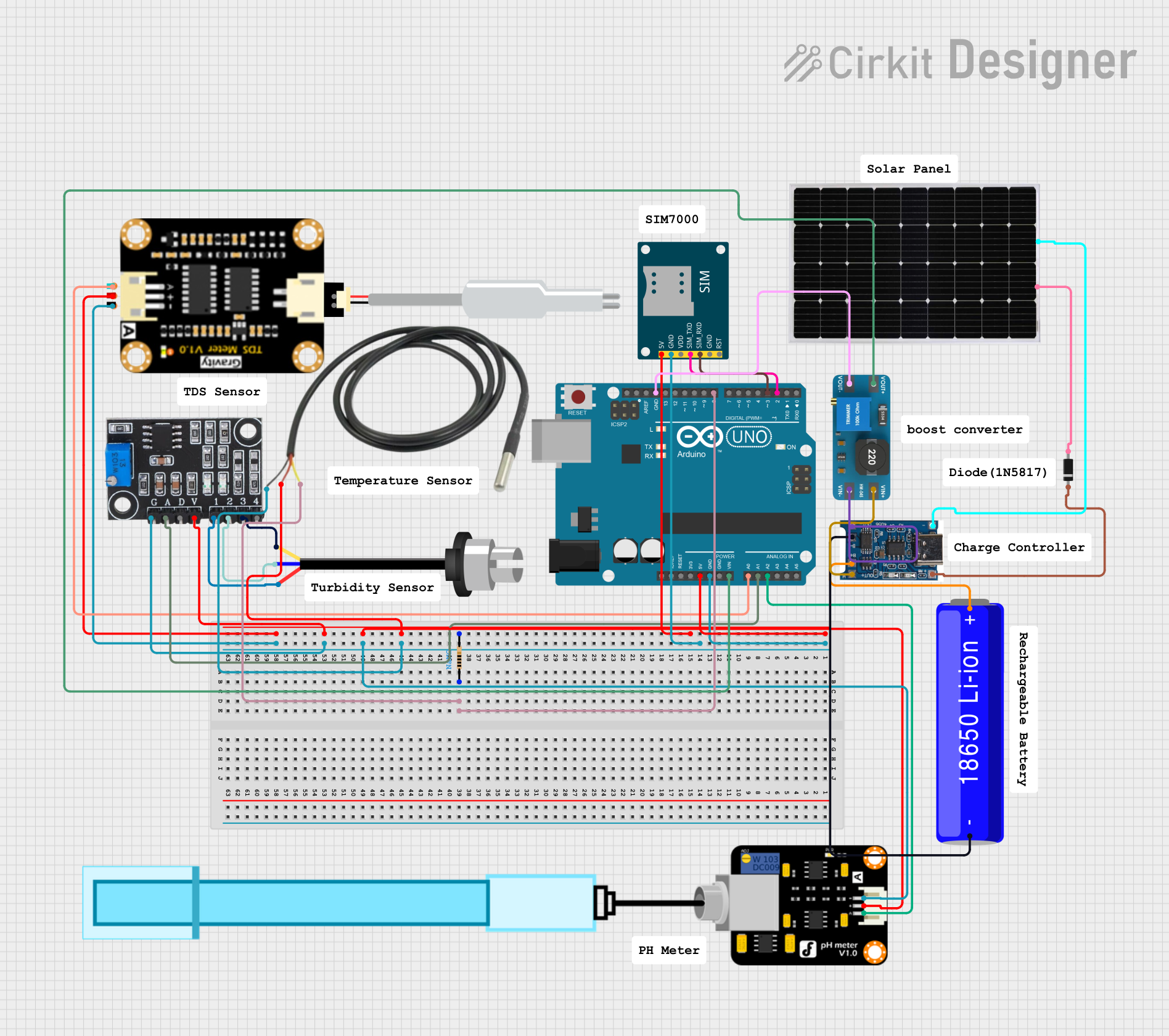 Open Project in Cirkit Designer
Explore Projects Built with Telemetria
Open Project in Cirkit DesignerOpen Project in Cirkit DesignerOpen Project in Cirkit DesignerOpen Project in Cirkit DesignerCommon Applications and Use Cases
- Environmental Monitoring: Collecting data on temperature, humidity, air quality, and water levels.
- Industrial Automation: Monitoring machinery performance and detecting faults in real-time.
- Healthcare: Remote patient monitoring for vital signs such as heart rate and blood pressure.
- Transportation: Fleet tracking and vehicle diagnostics.
- Energy Management: Monitoring power grids, solar panels, and wind turbines.
Technical Specifications
The technical specifications of a Telemetria system can vary depending on the specific implementation. Below are general specifications for a typical Telemetria module:
Key Technical Details
- Operating Voltage: 3.3V to 5V
- Communication Protocols: UART, SPI, I2C, or wireless (e.g., LoRa, Zigbee, GSM)
- Data Transmission Range: Up to 10 km (depending on the communication technology)
- Power Consumption: 50 mW to 500 mW (varies with usage)
- Supported Sensors: Analog and digital sensors
- Operating Temperature: -40°C to 85°C
- Data Rate: Up to 115200 bps (for UART-based systems)
Pin Configuration and Descriptions
Below is a typical pinout for a Telemetria module:
| Pin | Name | Description |
|---|---|---|
| 1 | VCC | Power supply input (3.3V or 5V, depending on the module) |
| 2 | GND | Ground connection |
| 3 | TX | Transmit data pin (UART communication) |
| 4 | RX | Receive data pin (UART communication) |
| 5 | SCL | Serial Clock Line for I2C communication |
| 6 | SDA | Serial Data Line for I2C communication |
| 7 | CS | Chip Select for SPI communication |
| 8 | IRQ | Interrupt Request pin for event-driven communication |
| 9 | ANT | Antenna connection for wireless communication (if applicable) |
Usage Instructions
How to Use the Component in a Circuit
- Power the Module: Connect the VCC pin to a 3.3V or 5V power source and the GND pin to the ground.
- Connect Communication Lines: Depending on the communication protocol:
- For UART: Connect the TX pin of the module to the RX pin of the microcontroller and vice versa.
- For I2C: Connect the SCL and SDA pins to the corresponding pins on the microcontroller.
- For SPI: Connect the CS, SCL, and data pins as per the SPI configuration.
- Attach Sensors: Connect the sensors to the appropriate analog or digital input pins.
- Configure the Module: Use the microcontroller to initialize and configure the Telemetria module for data transmission.
- Monitor Data: Use a central system or cloud platform to receive and analyze the transmitted data.
Important Considerations and Best Practices
- Ensure the power supply voltage matches the module's requirements to avoid damage.
- Use proper shielding and grounding to minimize interference in wireless communication.
- For long-range communication, ensure the antenna is properly connected and positioned.
- Regularly update the firmware of the module to ensure compatibility and security.
- Test the system in a controlled environment before deploying it in the field.
Example Code for Arduino UNO
Below is an example of how to use a Telemetria module with an Arduino UNO via UART:
#include <SoftwareSerial.h>

// Define RX and TX pins for the Telemetria module
SoftwareSerial telemetriaSerial(10, 11); // RX = pin 10, TX = pin 11

void setup() {
  Serial.begin(9600); // Initialize Serial Monitor
  telemetriaSerial.begin(9600); // Initialize Telemetria module communication

  Serial.println("Telemetria Module Initialized");
}

void loop() {
  // Send data to the Telemetria module
  telemetriaSerial.println("Hello from Arduino!");

  // Check if data is available from the Telemetria module
  if (telemetriaSerial.available()) {
    String receivedData = telemetriaSerial.readString();
    Serial.print("Received: ");
    Serial.println(receivedData); // Print received data to Serial Monitor
  }

  delay(1000); // Wait for 1 second before sending the next message
}
Troubleshooting and FAQs
Common Issues Users Might Face
No Data Transmission:
- Cause: Incorrect wiring or mismatched baud rate.
- Solution: Double-check the wiring and ensure the baud rate in the code matches the module's settings.
Interference in Wireless Communication:
- Cause: Nearby devices operating on the same frequency.
- Solution: Change the frequency/channel or use proper shielding.
Module Not Powering On:
- Cause: Insufficient power supply or incorrect voltage.
- Solution: Verify the power supply voltage and current ratings.
Data Loss or Corruption:
- Cause: Long transmission distances or poor signal quality.
- Solution: Use repeaters or stronger antennas for long-range communication.
Solutions and Tips for Troubleshooting
- Use a multimeter to verify power supply connections.
- Test the module with a simple setup before integrating it into a complex system.
- Check the module's datasheet for specific configuration details.
- Update the microcontroller's firmware and libraries to the latest versions.
By following this documentation, users can effectively integrate and troubleshoot a Telemetria module in their projects.