
How to Use US-100 Ultrasonic Distance Sensor: Examples, Pinouts, and Specs

 Design with US-100 Ultrasonic Distance Sensor in Cirkit Designer
Introduction
The US-100 is an ultrasonic distance sensor designed to measure distances by emitting ultrasonic waves and calculating the time it takes for the echo to return. This sensor is widely used in robotics, automation, and IoT applications for tasks such as obstacle detection, distance measurement, and object tracking. Its versatility and ease of use make it a popular choice for both hobbyists and professionals.
Explore Projects Built with US-100 Ultrasonic Distance Sensor
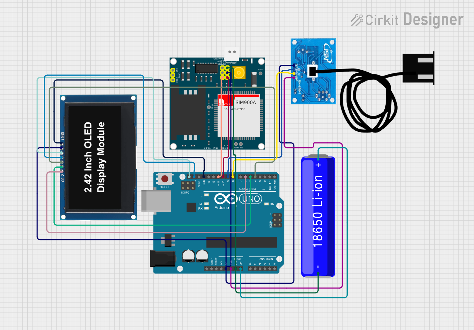 Open Project in Cirkit Designer
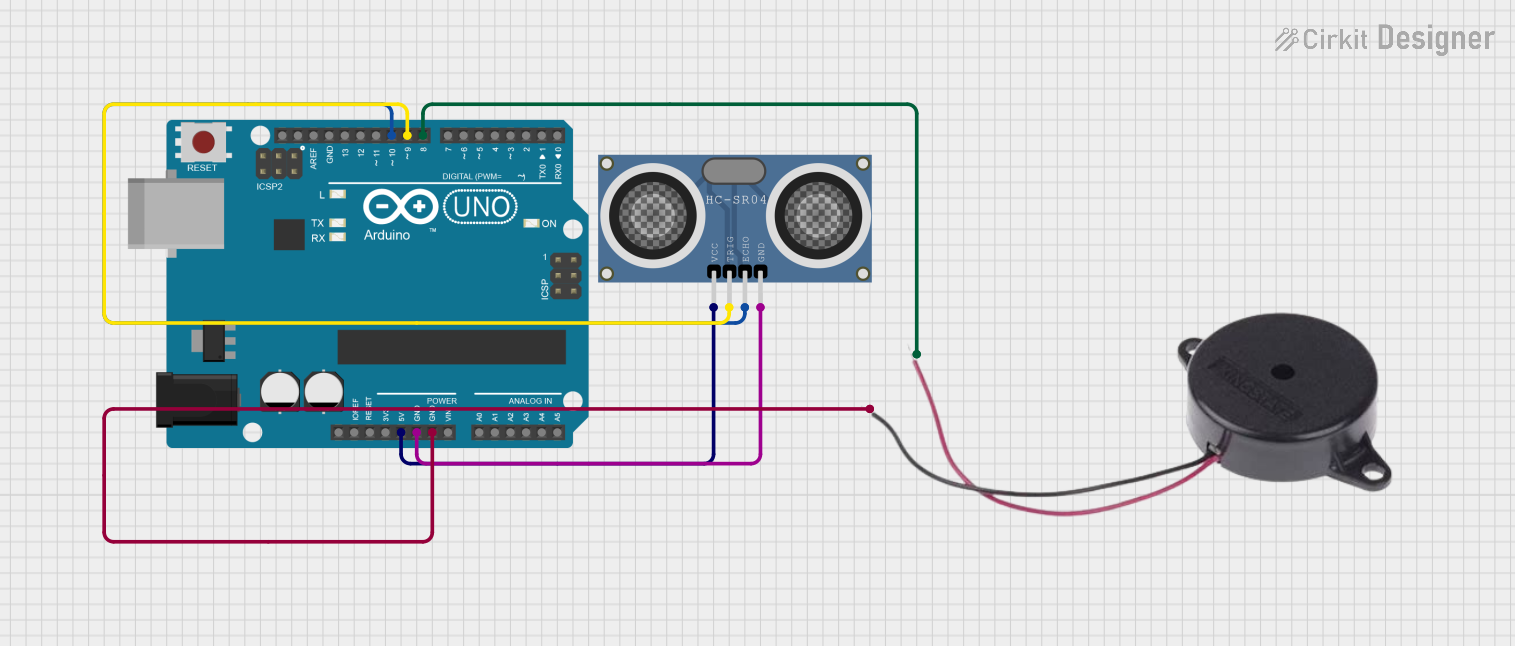 Open Project in Cirkit Designer
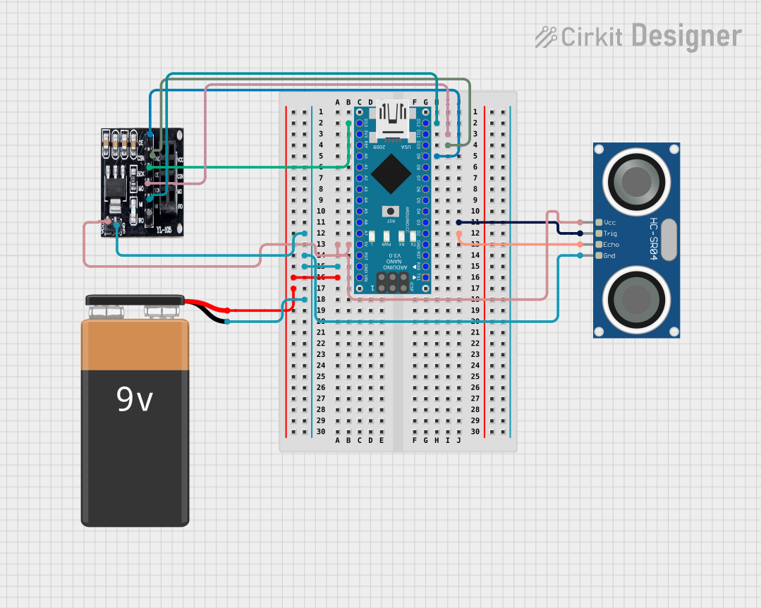 Open Project in Cirkit Designer
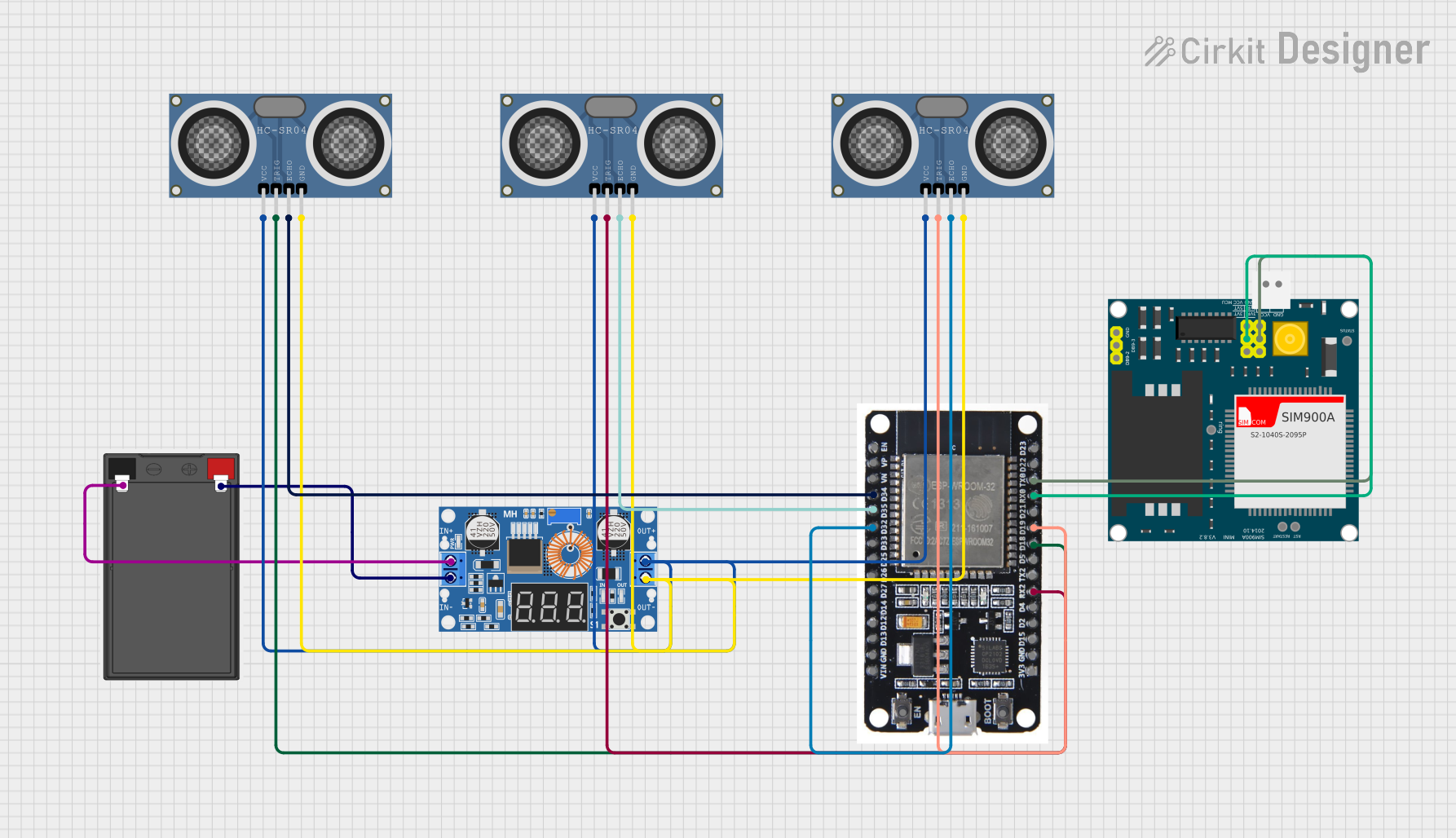 Open Project in Cirkit Designer
Explore Projects Built with US-100 Ultrasonic Distance Sensor
Open Project in Cirkit DesignerOpen Project in Cirkit DesignerOpen Project in Cirkit DesignerOpen Project in Cirkit DesignerCommon Applications:
- Obstacle detection in robotics
- Distance measurement in automation systems
- Liquid level sensing
- Proximity detection in security systems
- Object tracking in IoT devices
Technical Specifications
The US-100 sensor offers both serial and pulse-width modulation (PWM) modes for distance measurement, making it highly adaptable to various applications.
Key Technical Details:
- Operating Voltage: 2.4V to 5.5V DC
- Operating Current: ~2mA
- Measuring Range: 2cm to 450cm
- Accuracy: ±0.3cm
- Communication Modes: Serial (UART) and PWM
- Operating Temperature: -20°C to 70°C
- Dimensions: 45mm x 20mm x 15mm
Pin Configuration and Descriptions:
The US-100 sensor has 4 pins, as described in the table below:
| Pin Number | Pin Name | Description |
|---|---|---|
| 1 | VCC | Power supply input (2.4V to 5.5V DC). |
| 2 | Trig/TX | Trigger pin for PWM mode or TX pin for serial communication. |
| 3 | Echo/RX | Echo pin for PWM mode or RX pin for serial communication. |
| 4 | GND | Ground connection. |
Note: The mode of operation (PWM or serial) is determined by the connection setup. If the Echo pin is left unconnected, the sensor operates in serial mode by default.
Usage Instructions
Using the US-100 in a Circuit:
- Power the Sensor: Connect the VCC pin to a 5V power source (or 3.3V if using a 3.3V system) and the GND pin to ground.
- Select the Mode:
- For PWM mode, connect the Trig pin to a microcontroller's digital output pin and the Echo pin to a digital input pin.
- For Serial mode, connect the TX pin to the RX pin of the microcontroller and the RX pin to the TX pin of the microcontroller.
- Trigger the Sensor:
- In PWM mode, send a 10µs HIGH pulse to the Trig pin to initiate a measurement.
- In serial mode, send the appropriate command (e.g.,
0x55) to request a distance reading.
- Read the Output:
- In PWM mode, measure the duration of the HIGH pulse on the Echo pin to calculate the distance.
- In serial mode, read the distance value directly from the sensor's TX pin.
Important Considerations:
- Ensure the sensor is mounted securely and aligned properly for accurate measurements.
- Avoid placing the sensor near ultrasonic noise sources, as this may interfere with readings.
- Use a capacitor (e.g., 10µF) across the VCC and GND pins to stabilize the power supply.
Example Code for Arduino UNO (PWM Mode):
// US-100 Ultrasonic Distance Sensor - PWM Mode Example
// This code measures distance using the US-100 sensor in PWM mode
// and displays the result in the Serial Monitor.

#define TRIG_PIN 9  // Define the Trig pin
#define ECHO_PIN 10 // Define the Echo pin

void setup() {
  pinMode(TRIG_PIN, OUTPUT); // Set Trig pin as output
  pinMode(ECHO_PIN, INPUT);  // Set Echo pin as input
  Serial.begin(9600);        // Initialize serial communication
}

void loop() {
  // Send a 10µs HIGH pulse to the Trig pin
  digitalWrite(TRIG_PIN, LOW);
  delayMicroseconds(2);
  digitalWrite(TRIG_PIN, HIGH);
  delayMicroseconds(10);
  digitalWrite(TRIG_PIN, LOW);

  // Measure the duration of the HIGH pulse on the Echo pin
  long duration = pulseIn(ECHO_PIN, HIGH);

  // Calculate the distance in cm
  float distance = duration * 0.034 / 2;

  // Print the distance to the Serial Monitor
  Serial.print("Distance: ");
  Serial.print(distance);
  Serial.println(" cm");

  delay(500); // Wait for 500ms before the next measurement
}
Example Code for Arduino UNO (Serial Mode):
// US-100 Ultrasonic Distance Sensor - Serial Mode Example
// This code reads distance data from the US-100 sensor in serial mode
// and displays the result in the Serial Monitor.

#define RX_PIN 10 // Define the RX pin for the sensor
#define TX_PIN 11 // Define the TX pin for the sensor

#include <SoftwareSerial.h>
SoftwareSerial us100(RX_PIN, TX_PIN); // Create a SoftwareSerial object

void setup() {
  Serial.begin(9600);       // Initialize serial communication
  us100.begin(9600);        // Initialize the US-100 sensor at 9600 baud
}

void loop() {
  us100.write(0x55);        // Send the command to request a distance reading
  delay(100);               // Wait for the sensor to process the command

  if (us100.available() >= 2) { // Check if at least 2 bytes are available
    int highByte = us100.read(); // Read the high byte
    int lowByte = us100.read();  // Read the low byte
    int distance = (highByte << 8) + lowByte; // Combine the bytes into a distance value

    Serial.print("Distance: ");
    Serial.print(distance);
    Serial.println(" mm");
  }

  delay(500); // Wait for 500ms before the next measurement
}
Troubleshooting and FAQs
Common Issues:
No Output or Incorrect Readings:
- Ensure the sensor is powered correctly and the connections are secure.
- Verify that the Trig and Echo pins (or TX and RX pins) are connected to the correct microcontroller pins.
- Check for interference from nearby ultrasonic sources.
Unstable Measurements:
- Add a capacitor (e.g., 10µF) across the VCC and GND pins to stabilize the power supply.
- Ensure the sensor is not obstructed or tilted.
Serial Communication Not Working:
- Confirm that the baud rate is set to 9600 in both the sensor and the microcontroller.
- Check the TX and RX pin connections.
FAQs:
Q: Can the US-100 measure distances below 2cm?
A: No, the minimum measurable distance is 2cm. Objects closer than this may not be detected accurately.
Q: How do I switch between PWM and serial modes?
A: The mode is determined by the connection setup. Leave the Echo pin unconnected for serial mode, or connect it for PWM mode.
Q: Can I use the US-100 with a 3.3V microcontroller?
A: Yes, the US-100 operates at voltages as low as 2.4V, making it compatible with 3.3V systems.