How to Use KT0803: Examples, Pinouts, and Specs
Introduction
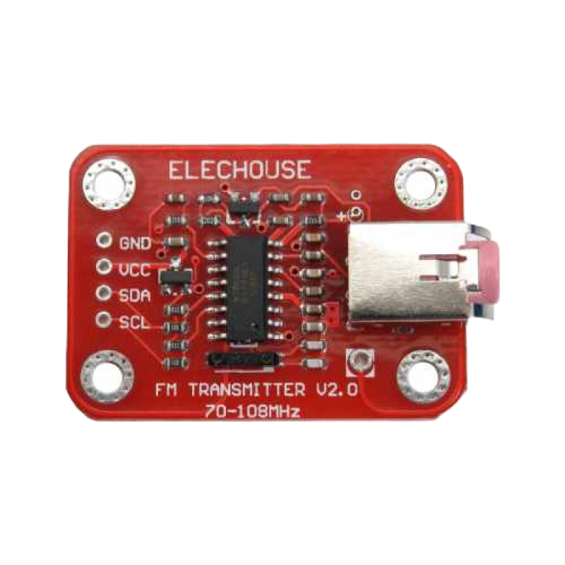
The KT0803, manufactured by ELECHOUSE, is a high-performance FM transmitter module designed for precision signal processing applications. It is widely used in audio transmission, wireless communication, and low-power FM broadcasting. The module features low offset voltage, low noise, and a wide bandwidth, making it ideal for high-quality audio transmission and other signal processing tasks.
Explore Projects Built with KT0803


Explore Projects Built with KT0803
Common Applications and Use Cases
- Wireless audio transmission for home or car audio systems
- Low-power FM broadcasting for personal or educational purposes
- Audio signal processing in instrumentation and control systems
- DIY electronics projects involving FM transmission
Technical Specifications
The KT0803 FM Transmitter Module is designed to deliver reliable performance with minimal power consumption. Below are its key technical specifications:
| Parameter | Value |
|---|---|
| Operating Voltage | 2.7V to 3.6V |
| Operating Current | 20mA (typical) |
| Frequency Range | 70 MHz to 108 MHz |
| Modulation Type | FM (Frequency Modulation) |
| Audio Input Impedance | 10 kΩ |
| Output Power | -15 dBm to 0 dBm |
| Signal-to-Noise Ratio | >60 dB |
| Harmonic Suppression | >40 dB |
| Operating Temperature | -40°C to +85°C |
| Package Type | SOP16 |
Pin Configuration and Descriptions
The KT0803 module has 16 pins, each serving a specific function. Below is the pin configuration:
| Pin Number | Pin Name | Description |
|---|---|---|
| 1 | VDD | Power supply input (2.7V to 3.6V) |
| 2 | GND | Ground connection |
| 3 | RFIN | RF input for external antenna |
| 4 | RFOUT | RF output for FM transmission |
| 5 | NC | No connection |
| 6 | NC | No connection |
| 7 | AUDIO_L | Left audio input |
| 8 | AUDIO_R | Right audio input |
| 9 | NC | No connection |
| 10 | NC | No connection |
| 11 | SCL | I2C clock line for communication |
| 12 | SDA | I2C data line for communication |
| 13 | NC | No connection |
| 14 | NC | No connection |
| 15 | NC | No connection |
| 16 | NC | No connection |
Usage Instructions
How to Use the KT0803 in a Circuit
- Power Supply: Connect the VDD pin to a stable power source (2.7V to 3.6V) and the GND pin to ground.
- Audio Input: Connect the left and right audio signals to the AUDIO_L and AUDIO_R pins, respectively. Ensure the audio signals are within the module's input impedance range (10 kΩ).
- Antenna: Attach an external antenna to the RFOUT pin to enable FM transmission. The antenna should be tuned for the desired frequency range (70 MHz to 108 MHz).
- I2C Communication: Use the SCL and SDA pins to configure the module via an I2C interface. This allows you to set the transmission frequency and other parameters.
Important Considerations and Best Practices
- Power Supply Stability: Use a low-noise power supply to avoid interference with the transmitted signal.
- Antenna Design: Ensure the antenna is properly designed and positioned to maximize transmission range and minimize interference.
- Frequency Selection: Choose a transmission frequency that does not conflict with local FM radio stations.
- Audio Signal Quality: Use high-quality audio sources to ensure clear and distortion-free transmission.
Example: Connecting the KT0803 to an Arduino UNO
The KT0803 can be controlled using an Arduino UNO via the I2C interface. Below is an example code snippet to set the transmission frequency:
#include <Wire.h> // Include the Wire library for I2C communication

#define KT0803_I2C_ADDRESS 0x3E // I2C address of the KT0803 module

void setup() {
  Wire.begin(); // Initialize I2C communication
  Serial.begin(9600); // Initialize serial communication for debugging

  // Set the transmission frequency to 100.1 MHz
  setFrequency(100.1);
}

void loop() {
  // Main loop does nothing in this example
}

void setFrequency(float frequency) {
  uint16_t freqWord = (frequency - 70.0) * 100; // Convert frequency to register value
  Wire.beginTransmission(KT0803_I2C_ADDRESS);
  Wire.write(0x00); // Address of the frequency register
  Wire.write((freqWord >> 8) & 0xFF); // High byte of the frequency word
  Wire.write(freqWord & 0xFF); // Low byte of the frequency word
  Wire.endTransmission();

  Serial.print("Frequency set to: ");
  Serial.print(frequency);
  Serial.println(" MHz");
}
Notes:
- Ensure the KT0803 module is properly connected to the Arduino UNO's I2C pins (SCL to A5, SDA to A4).
- Modify the
setFrequencyfunction to set a different transmission frequency as needed.
Troubleshooting and FAQs
Common Issues and Solutions
No Signal Transmission
- Cause: Incorrect antenna connection or configuration.
- Solution: Verify the antenna is properly connected to the RFOUT pin and is tuned for the desired frequency range.
Poor Audio Quality
- Cause: Low-quality audio source or interference.
- Solution: Use a high-quality audio source and ensure the power supply is stable and noise-free.
I2C Communication Failure
- Cause: Incorrect wiring or I2C address.
- Solution: Double-check the connections to the SCL and SDA pins and ensure the correct I2C address (0x3E) is used.
Overlapping with Local FM Stations
- Cause: Selected frequency conflicts with an existing FM station.
- Solution: Choose a different frequency that is not in use in your area.
FAQs
Can the KT0803 operate at higher voltages?
- No, the KT0803 is designed to operate within a voltage range of 2.7V to 3.6V. Exceeding this range may damage the module.
What is the maximum transmission range of the KT0803?
- The transmission range depends on the antenna design and environmental conditions. Typically, it can transmit up to 10-20 meters with a properly tuned antenna.
Is the KT0803 compatible with other microcontrollers?
- Yes, the KT0803 can be used with any microcontroller that supports I2C communication, such as the ESP32, STM32, or Raspberry Pi.
Can I use the KT0803 for stereo audio transmission?
- Yes, the KT0803 supports stereo audio input via the AUDIO_L and AUDIO_R pins.