
How to Use COMPUTER-PERIPHERAL-POWER: Examples, Pinouts, and Specs
 Design with COMPUTER-PERIPHERAL-POWER in Cirkit Designer
Introduction
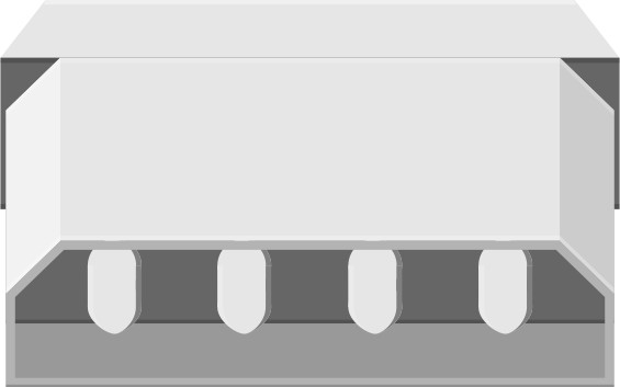
The 4-Pin Peripheral Power Connector, manufactured by Molex, is a widely used power supply unit designed to provide electrical power to computer peripherals. This connector ensures efficient and reliable operation of devices such as hard drives, optical drives, and other internal components in desktop computers. Its robust design and standardized pin configuration make it a staple in legacy and modern systems requiring stable power delivery.
Explore Projects Built with COMPUTER-PERIPHERAL-POWER
 Open Project in Cirkit Designer
 Open Project in Cirkit Designer
 Open Project in Cirkit Designer
 Open Project in Cirkit Designer
Explore Projects Built with COMPUTER-PERIPHERAL-POWER
Open Project in Cirkit DesignerOpen Project in Cirkit DesignerOpen Project in Cirkit DesignerOpen Project in Cirkit DesignerCommon Applications and Use Cases
- Powering internal hard disk drives (HDDs) and optical drives (CD/DVD drives).
- Supplying power to cooling fans and other internal computer peripherals.
- Used in custom PC builds and repairs for legacy systems.
- Providing power to adapters or converters for modern SATA devices.
Technical Specifications
Key Technical Details
- Manufacturer: Molex
- Part ID: 4-Pin Peripheral Power Connector
- Voltage Ratings: +12V (Yellow wire), +5V (Red wire)
- Current Rating: Up to 11A per pin (depending on wire gauge)
- Connector Type: Male and female, 4-pin
- Wire Gauge: Typically 18 AWG
- Operating Temperature: -40°C to +105°C
- Durability: Rated for 50 mating cycles
Pin Configuration and Descriptions
The 4-pin peripheral power connector has a standardized pinout, as detailed below:
| Pin Number | Wire Color | Voltage | Description |
|---|---|---|---|
| 1 | Yellow | +12V | Supplies +12V power |
| 2 | Black | Ground | Ground connection |
| 3 | Black | Ground | Ground connection |
| 4 | Red | +5V | Supplies +5V power |
Usage Instructions
How to Use the Component in a Circuit
- Identify the Connector: Locate the 4-pin peripheral power connector on your power supply unit (PSU). It is typically a white plastic connector with four wires (yellow, red, and two black).
- Connect to the Peripheral: Align the connector with the corresponding port on the peripheral device (e.g., HDD or optical drive). Ensure the connector is inserted securely to avoid loose connections.
- Power On the System: Once all connections are made, power on the computer to supply electricity to the connected peripherals.
Important Considerations and Best Practices
- Compatibility: Ensure the peripheral device is compatible with the 4-pin connector. Modern devices may require SATA power connectors, which can be adapted using Molex-to-SATA adapters.
- Avoid Overloading: Do not exceed the current rating of the connector. Overloading can cause overheating and damage to the wires or connected devices.
- Cable Management: Use cable ties or clips to organize wires and prevent accidental disconnections or damage.
- Inspect for Damage: Regularly check the connector and wires for signs of wear, such as fraying or discoloration, which could indicate overheating or poor connections.
Example: Connecting to an Arduino UNO
While the 4-pin peripheral power connector is not directly compatible with Arduino boards, it can be used to power external components in Arduino projects. For example, you can use a Molex-to-barrel jack adapter to power a motor driver or other high-power peripherals.
// Example Arduino code to control a motor powered by a Molex 4-pin connector
// Ensure the motor driver is connected to the Molex +12V and GND lines

const int motorPin = 9; // PWM pin connected to motor driver input

void setup() {
  pinMode(motorPin, OUTPUT); // Set motor pin as output
}

void loop() {
  analogWrite(motorPin, 128); // Run motor at 50% speed
  delay(5000);               // Keep motor running for 5 seconds
  analogWrite(motorPin, 0);  // Stop motor
  delay(2000);               // Wait for 2 seconds before restarting
}
Note: Ensure proper voltage regulation when using the 4-pin connector to power Arduino-related components.
Troubleshooting and FAQs
Common Issues Users Might Face
- Loose Connections: The connector may not fit securely into the peripheral device, leading to intermittent power delivery.
- Solution: Ensure the connector is fully inserted and properly aligned with the device port.
- Overheating Wires: Excessive current draw can cause the wires to overheat.
- Solution: Verify the current requirements of connected devices and avoid exceeding the connector's current rating.
- Device Not Powering On: The peripheral device does not receive power.
- Solution: Check the PSU for proper functionality and ensure the connector is not damaged.
FAQs
Q: Can I use the 4-pin connector to power modern SATA devices?
A: Yes, with a Molex-to-SATA power adapter, you can connect SATA devices to the 4-pin connector.Q: What happens if I reverse the connector?
A: The 4-pin connector is keyed to prevent incorrect insertion. Forcing it in the wrong orientation may damage the connector or device.Q: Can I split the 4-pin connector to power multiple devices?
A: Yes, but ensure the total current draw does not exceed the PSU's or connector's rating.
By following this documentation, users can effectively utilize the Molex 4-pin Peripheral Power Connector in their systems and projects.