How to Use ADXXL335: Examples, Pinouts, and Specs
Introduction
The ADXL335 is a small, thin, low-power, 3-axis accelerometer with signal conditioned voltage outputs. It measures acceleration with a minimum full-scale range of ±3 g. It can measure the static acceleration of gravity in tilt-sensing applications, as well as dynamic acceleration resulting from motion, shock, or vibration.
Explore Projects Built with ADXXL335

Explore Projects Built with ADXXL335
Common Applications and Use Cases
- Motion sensor for mobile devices
- Gaming and pointing devices
- Industrial instrumentation
- Robotics
- Tilt-sensing applications
Technical Specifications
Key Technical Details
- Power Supply: 1.8V to 3.6V DC
- Sensitivity: Typically 300 mV/g at 3V
- Measurement Range: ±3 g
- Bandwidth: 0.5 Hz to 1600 Hz
- Temperature Range: -40°C to +85°C
- Self-Test Feature
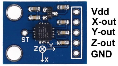
Pin Configuration and Descriptions
| Pin Number | Name | Description |
|---|---|---|
| 1 | VCC | Power supply (1.8V to 3.6V) |
| 2 | XOUT | X-axis output |
| 3 | YOUT | Y-axis output |
| 4 | ZOUT | Z-axis output |
| 5 | GND | Ground connection |
| 6 | ST | Self-test |
Usage Instructions
How to Use the ADXL335 in a Circuit
Powering the Device:
- Connect VCC to a 1.8V to 3.6V power supply.
- Connect GND to the system ground.
Reading the Outputs:
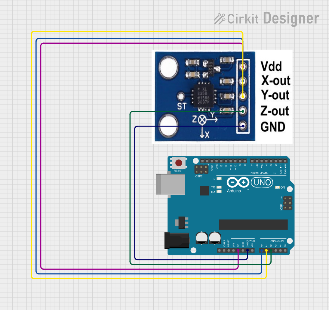
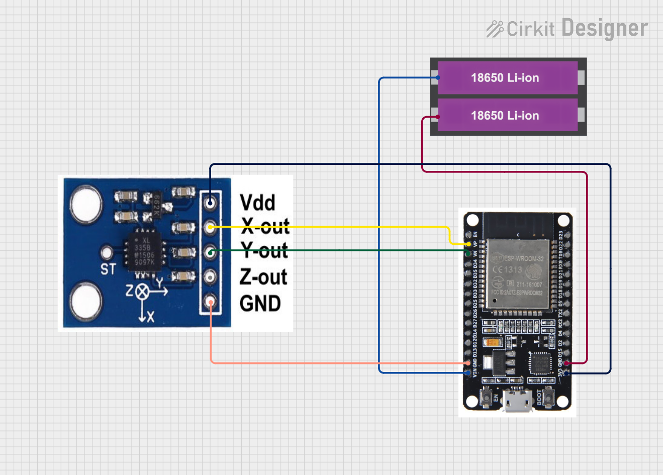
- Connect XOUT, YOUT, and ZOUT to analog inputs on your microcontroller, such as an Arduino UNO.
Calibration:
- Perform a calibration routine to account for zero-g offset and sensitivity.
Important Considerations and Best Practices
- Voltage Levels: Ensure that the power supply and I/O voltage levels are compatible with your microcontroller.
- Decoupling Capacitors: Use a 0.1 µF capacitor close to the VCC pin to filter out noise.
- Analog Inputs: Use analog inputs with sufficient resolution to capture the 13-bit output of the ADXL335.
- Mounting: Securely mount the ADXL335 to the object whose acceleration is being measured.
Example Code for Arduino UNO
// Include the Arduino core library
#include <Arduino.h>

// Define the analog pins connected to the accelerometer
const int xPin = A0;
const int yPin = A1;
const int zPin = A2;

void setup() {
  // Initialize the serial communication
  Serial.begin(9600);
}

void loop() {
  // Read the raw values from the accelerometer
  int xRaw = analogRead(xPin);
  int yRaw = analogRead(yPin);
  int zRaw = analogRead(zPin);

  // Convert the raw values to 'g' values
  float xG = (xRaw - 338.0) * (3.0 / 1023.0);
  float yG = (yRaw - 338.0) * (3.0 / 1023.0);
  float zG = (zRaw - 338.0) * (3.0 / 1023.0);

  // Print the acceleration 'g' values
  Serial.print("X: ");
  Serial.print(xG);
  Serial.print("g, Y: ");
  Serial.print(yG);
  Serial.print("g, Z: ");
  Serial.print(zG);
  Serial.println("g");

  // Delay before the next reading
  delay(100);
}
Note: The values 338.0 and 3.0/1023.0 in the code are based on a typical sensitivity and zero-g offset. These values should be calibrated for each ADXL335 device used.
Troubleshooting and FAQs
Common Issues Users Might Face
- Inaccurate Readings: Ensure that the accelerometer is properly calibrated.
- Noisy Signal: Use decoupling capacitors and keep the power supply stable.
- Device Not Responding: Check the connections and ensure the correct power supply voltage.
Solutions and Tips for Troubleshooting
- Calibration: Perform a calibration routine at startup and periodically during operation.
- Signal Filtering: Implement software filtering techniques to smooth out the data.
- Power Supply: Use a stable and clean power supply to minimize noise.
FAQs:
Q: Can the ADXL335 measure rotation?
- A: No, the ADXL335 is an accelerometer and measures linear acceleration. For rotation, you would need a gyroscope.
Q: What is the purpose of the self-test pin?
- A: The self-test pin (ST) can be used to verify the functionality of the accelerometer by applying a known force to the sensor.
Q: How do I convert the analog readings to 'g' values?
- A: The analog readings can be converted to 'g' values by first subtracting the zero-g offset and then scaling the result by the sensitivity factor. Calibration is necessary for accurate conversion.
Remember, this documentation is a starting point. For more detailed information, consult the ADXL335 datasheet and application notes provided by the manufacturer.