How to Use pixhawk: Examples, Pinouts, and Specs
Introduction
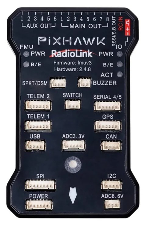
The Pixhawk 2.4.8, manufactured by ArduPilot, is an open-source flight control hardware designed for a wide range of autonomous vehicles, including drones, planes, and rovers. It is a highly versatile and reliable autopilot system that integrates advanced sensors, communication interfaces, and processing capabilities. The Pixhawk is widely used in robotics, unmanned aerial vehicles (UAVs), and other autonomous systems due to its robust performance and compatibility with various software platforms like ArduPilot and PX4.
Explore Projects Built with pixhawk

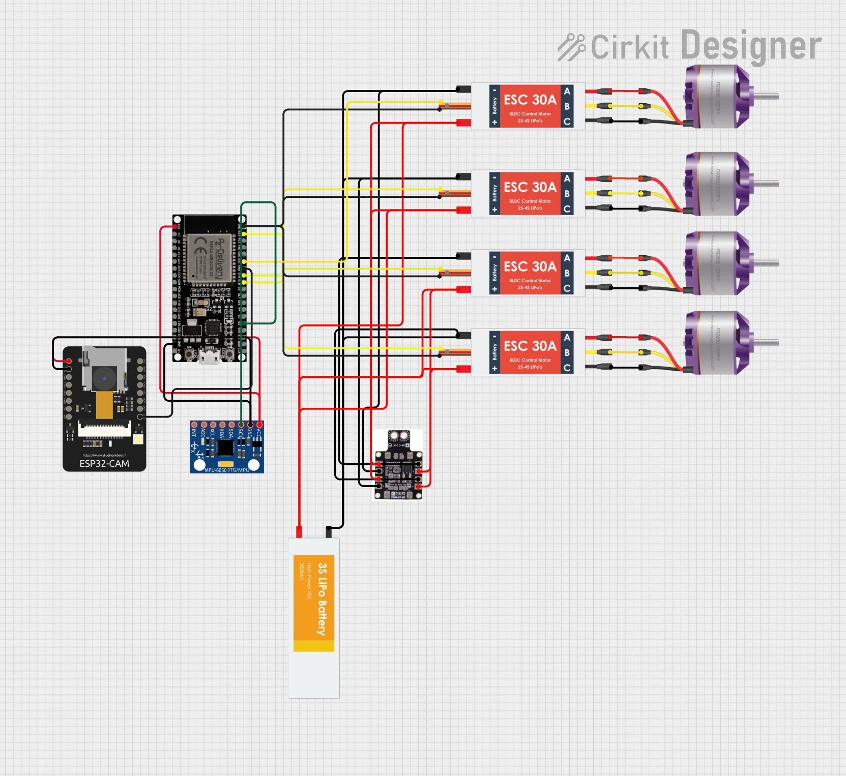
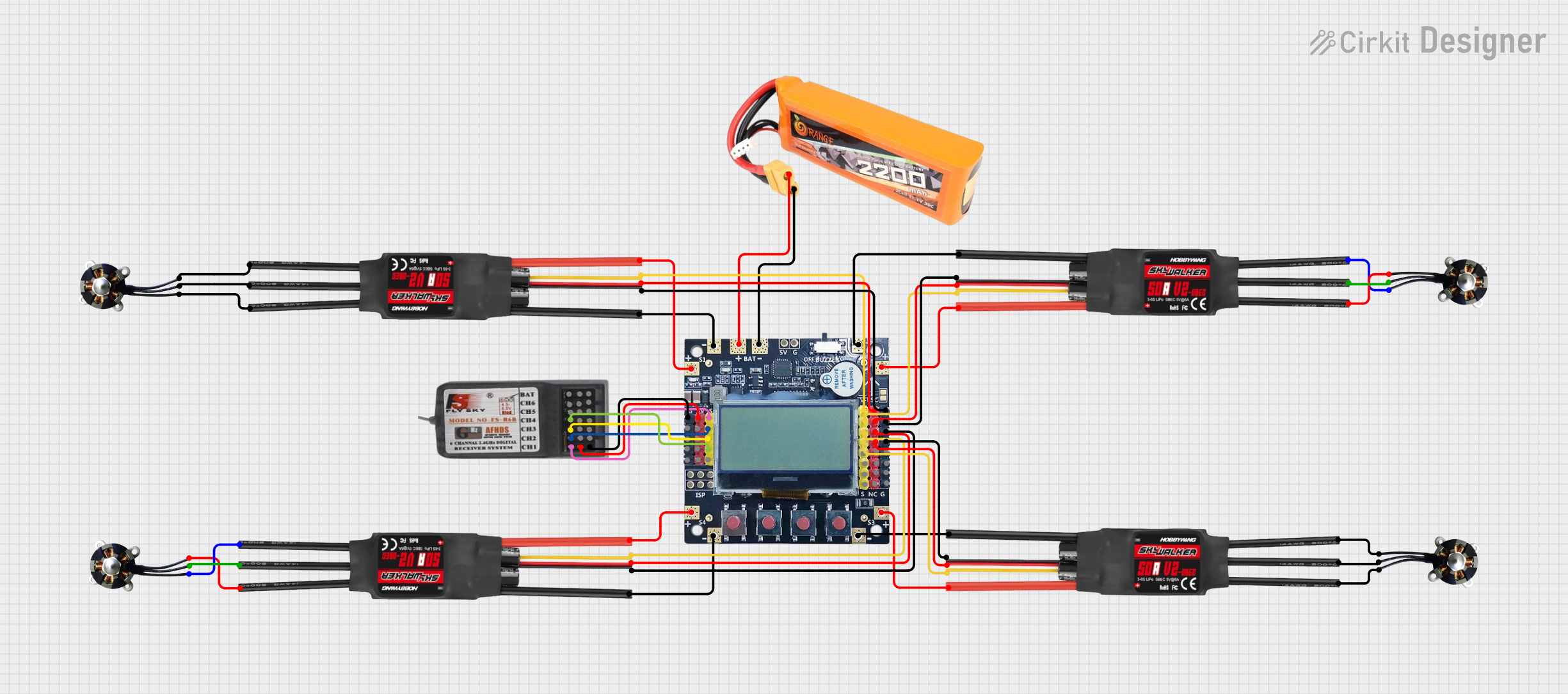
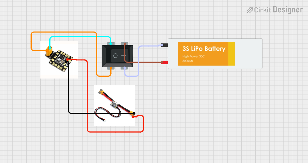
Explore Projects Built with pixhawk
Common Applications and Use Cases
- Multirotor drones for aerial photography, mapping, and surveying
- Fixed-wing aircraft for long-range missions
- Rovers for ground-based exploration and automation
- Autonomous boats and submarines
- Research and development in robotics and UAV technologies
Technical Specifications
The Pixhawk 2.4.8 is equipped with powerful hardware and a wide range of interfaces to support various sensors and peripherals. Below are the key technical details:
Key Technical Details
- Processor: 32-bit STM32F427 Cortex-M4 core with FPU
- IMU Sensors:
- MPU6000 (accelerometer and gyroscope)
- LSM303D (magnetometer)
- MS5611 (barometer)
- Input Voltage: 4.8V to 5.4V
- Power Consumption: ~280mA at 5V
- Communication Interfaces:
- UART, I2C, CAN, SPI, and USB
- PWM Outputs: 8 main outputs, 6 auxiliary outputs
- Storage: MicroSD card slot for data logging
- Dimensions: 50mm x 81.5mm x 15.5mm
- Weight: ~38g
Pin Configuration and Descriptions
The Pixhawk 2.4.8 features multiple connectors for peripherals and power. Below is a table summarizing the key pin configurations:
Power Input
| Pin Name | Description |
|---|---|
| Power (+) | Main power input (4.8V to 5.4V) |
| Power (-) | Ground connection |
PWM Outputs
| Pin Name | Description |
|---|---|
| MAIN OUT 1-8 | Main motor/servo outputs |
| AUX OUT 1-6 | Auxiliary motor/servo outputs |
Communication Interfaces
| Pin Name | Description |
|---|---|
| TELEM1 | Telemetry port 1 (UART) |
| TELEM2 | Telemetry port 2 (UART) |
| GPS | GPS module connection (UART + I2C) |
| I2C | I2C bus for external sensors |
| CAN | CAN bus for advanced peripherals |
| USB | USB port for configuration and data |
Other Connectors
| Pin Name | Description |
|---|---|
| RC IN | Input for RC receiver |
| SBUS | SBUS input for RC systems |
| Buzzer | Buzzer connection for alerts |
| Safety Switch | Safety switch input |
| MicroSD Slot | For data logging and firmware updates |
Usage Instructions
How to Use the Pixhawk 2.4.8 in a Circuit
- Powering the Pixhawk: Connect a power module to the "Power" port to supply 4.8V to 5.4V. Ensure the power source is stable and capable of providing sufficient current.
- Connecting Peripherals:
- Attach motors or servos to the MAIN OUT or AUX OUT pins.
- Connect a GPS module to the GPS port for navigation.
- Use the TELEM1 or TELEM2 ports to connect telemetry radios for communication with a ground control station.
- Attach additional sensors (e.g., rangefinders, cameras) to the I2C or CAN ports as needed.
- Configuring the System:
- Use a USB cable to connect the Pixhawk to a computer.
- Install and launch a ground control software like Mission Planner or QGroundControl.
- Follow the software's setup wizard to configure the vehicle type, calibrate sensors, and set up flight modes.
- Testing: Perform a pre-flight check to ensure all components are functioning correctly. Verify motor/servo outputs, sensor readings, and communication links.
Important Considerations and Best Practices
- Power Redundancy: Use a backup power source (e.g., a secondary battery) to ensure continuous operation in case of a primary power failure.
- Firmware Updates: Regularly update the firmware using Mission Planner or QGroundControl to access the latest features and bug fixes.
- Vibration Isolation: Mount the Pixhawk on vibration-dampening material to reduce noise in sensor readings.
- Safety: Always use the safety switch to arm/disarm the system and prevent accidental motor activation.
Example Code for Arduino UNO Integration
The Pixhawk can communicate with an Arduino UNO via the TELEM or I2C ports. Below is an example of how to read data from the Pixhawk using the MAVLink protocol:
#include <mavlink.h> // Include the MAVLink library

// Define the serial port for communication with Pixhawk
#define SERIAL_PORT Serial1

void setup() {
  Serial.begin(9600); // Initialize serial monitor
  SERIAL_PORT.begin(57600); // Initialize Pixhawk communication

  Serial.println("Starting communication with Pixhawk...");
}

void loop() {
  // Check if data is available from Pixhawk
  if (SERIAL_PORT.available()) {
    uint8_t byte = SERIAL_PORT.read(); // Read a byte from Pixhawk

    // Parse the MAVLink message
    mavlink_message_t msg;
    mavlink_status_t status;
    if (mavlink_parse_char(MAVLINK_COMM_0, byte, &msg, &status)) {
      // Print the message ID and payload length
      Serial.print("Received message ID: ");
      Serial.print(msg.msgid);
      Serial.print(", Payload length: ");
      Serial.println(msg.len);
    }
  }
}
Troubleshooting and FAQs
Common Issues and Solutions
Pixhawk Not Powering On
- Cause: Insufficient or unstable power supply.
- Solution: Verify the power module connection and ensure the input voltage is within the 4.8V to 5.4V range.
No GPS Lock
- Cause: Poor satellite visibility or incorrect GPS module connection.
- Solution: Move the GPS module to an open area with a clear view of the sky. Check the GPS port wiring.
Telemetry Not Working
- Cause: Incorrect baud rate or wiring.
- Solution: Ensure the telemetry radio is connected to the correct TELEM port and the baud rate matches the ground control station settings.
Motors Not Responding
- Cause: Incorrect motor wiring or calibration.
- Solution: Verify motor connections to the MAIN OUT pins and recalibrate the ESCs using the ground control software.
FAQs
Q: Can the Pixhawk 2.4.8 be used with PX4 firmware?
- A: Yes, the Pixhawk 2.4.8 is compatible with both ArduPilot and PX4 firmware.
Q: What is the maximum number of PWM outputs?
- A: The Pixhawk 2.4.8 supports up to 14 PWM outputs (8 main and 6 auxiliary).
Q: How do I reset the Pixhawk to factory settings?
- A: Use the ground control software to perform a parameter reset or reflash the firmware.
Q: Can I use the Pixhawk for indoor navigation?
- A: Yes, but you will need additional sensors like optical flow or LiDAR for accurate indoor positioning.