
How to Use MTD-450 DC 11-36V H-Bridge Brushed PWM Motor Driver Module: Examples, Pinouts, and Specs
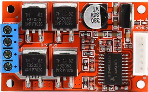
 Design with MTD-450 DC 11-36V H-Bridge Brushed PWM Motor Driver Module in Cirkit Designer
Introduction
The MTD-450 DC 11-36V H-Bridge Brushed PWM Motor Driver Module is a versatile and efficient motor driver designed to control brushed DC motors. It utilizes an H-bridge configuration, enabling bidirectional control of motor speed and direction through Pulse Width Modulation (PWM) signals. This module is ideal for applications requiring precise motor control, such as robotics, conveyor systems, and automated machinery.
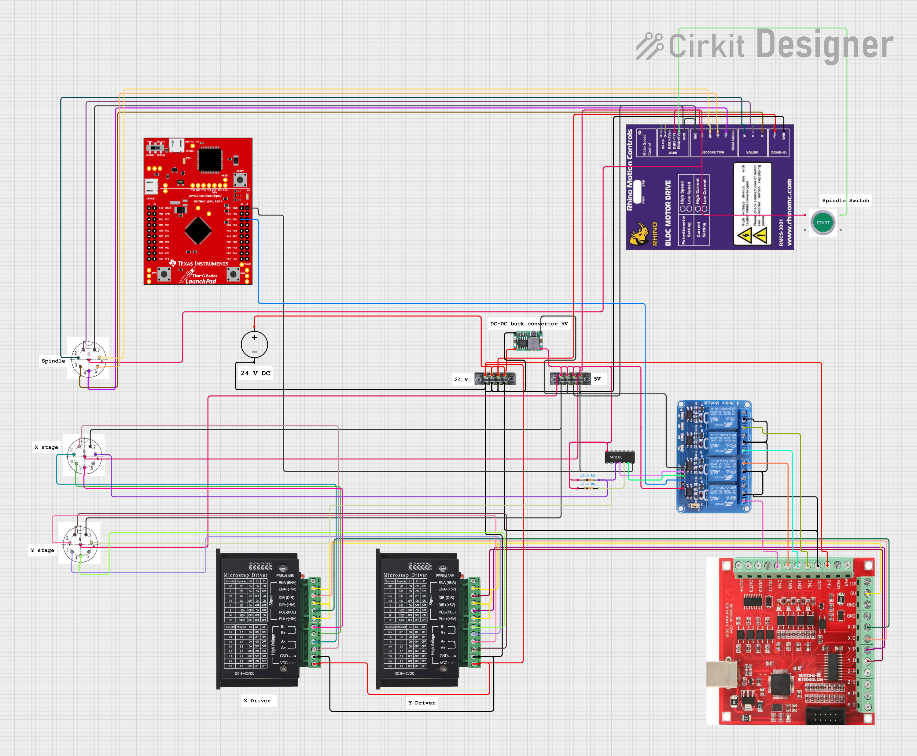
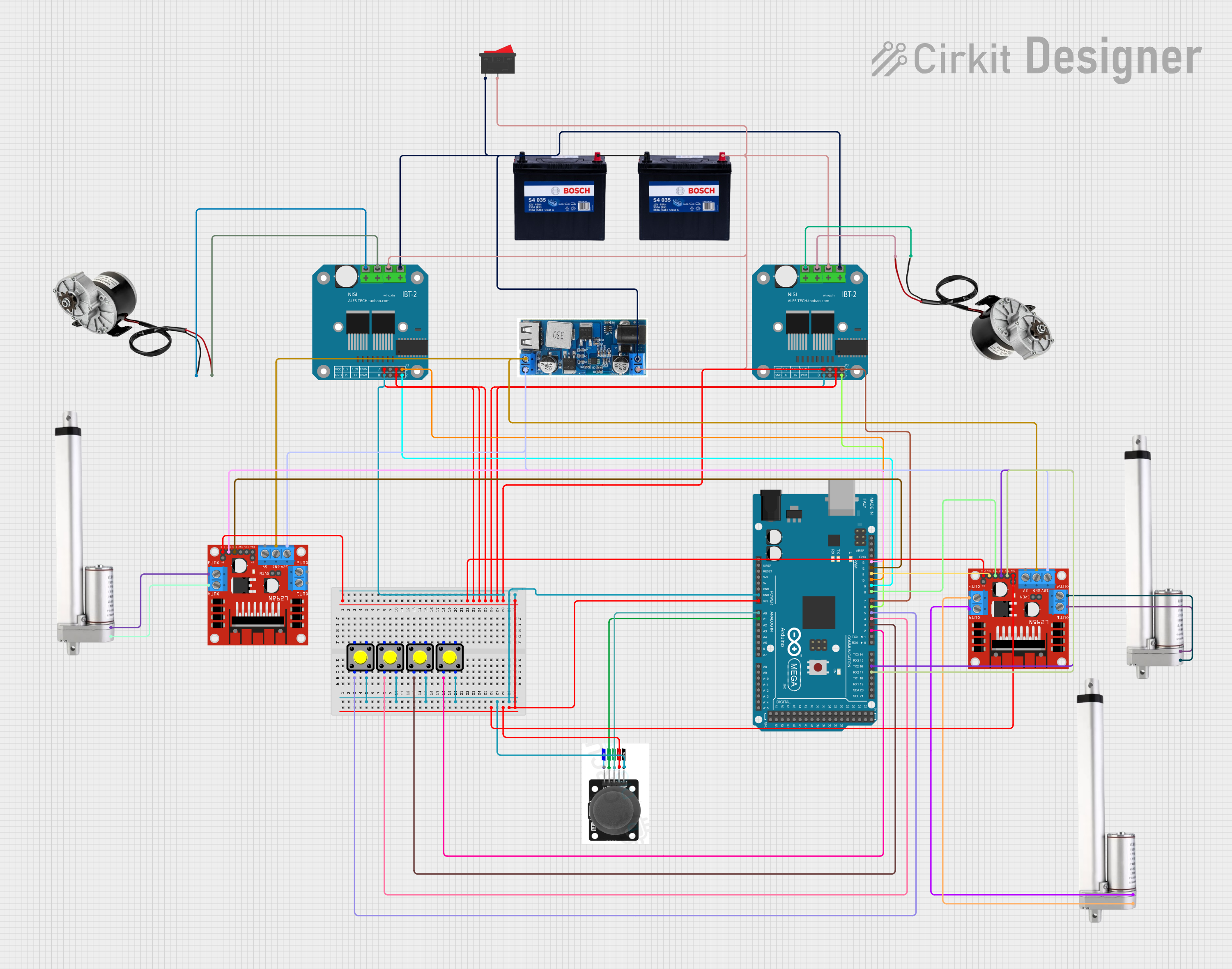
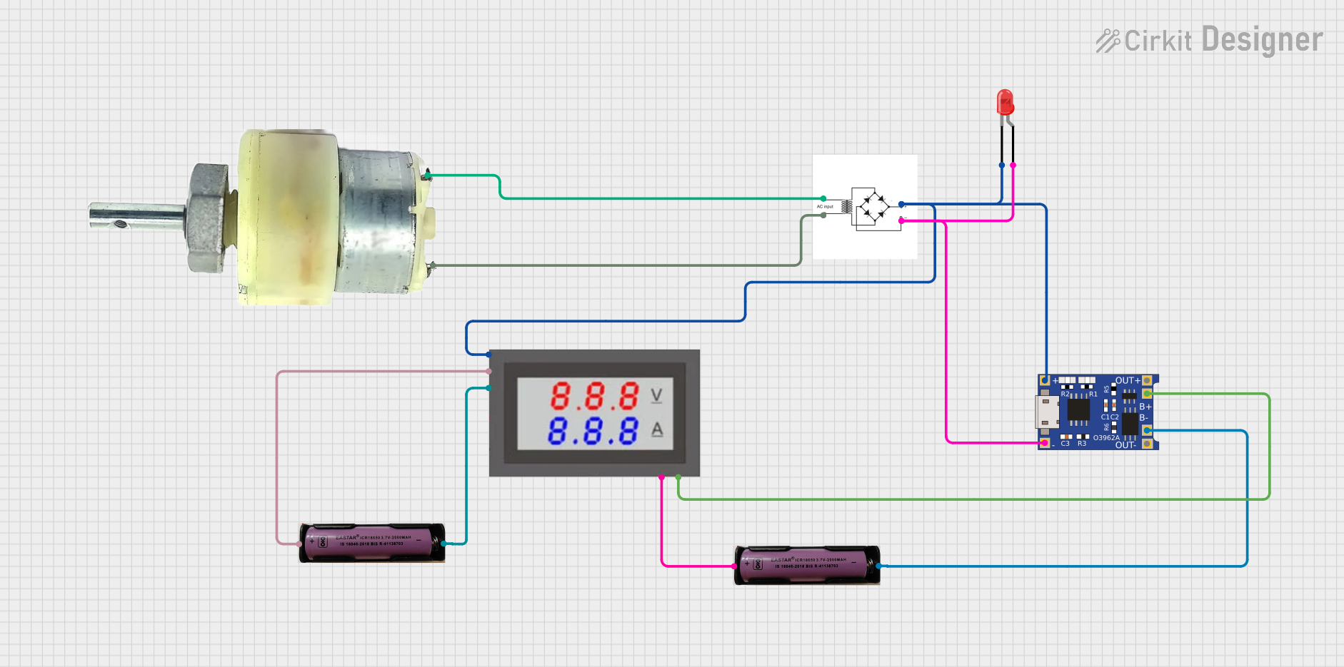
Explore Projects Built with MTD-450 DC 11-36V H-Bridge Brushed PWM Motor Driver Module
 Open Project in Cirkit Designer
 Open Project in Cirkit Designer
 Open Project in Cirkit Designer
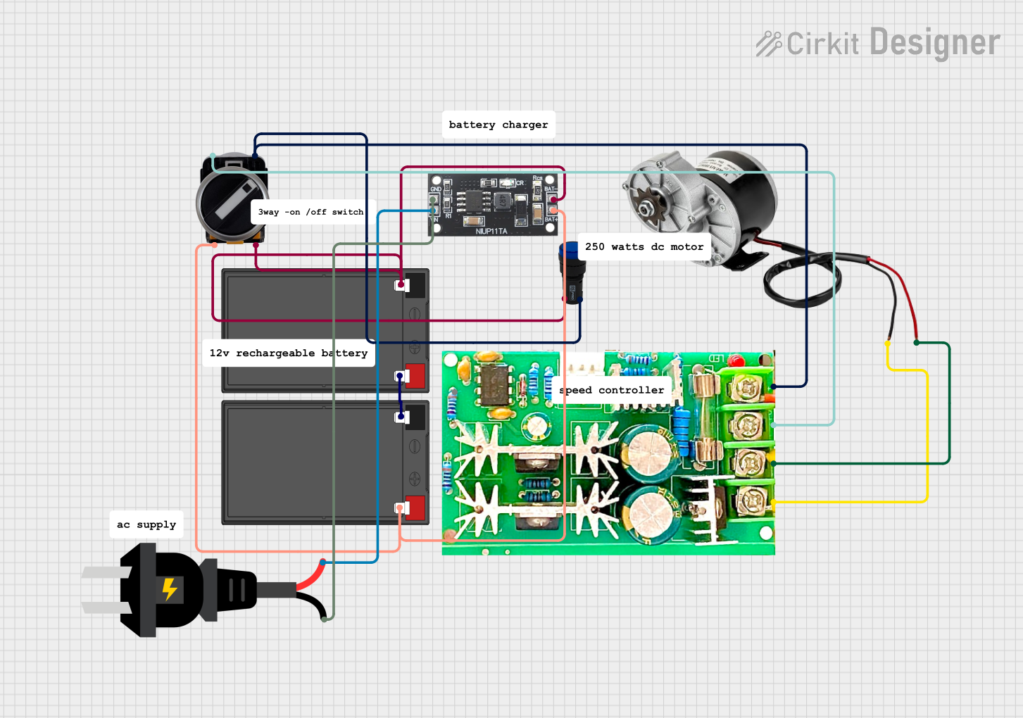 Open Project in Cirkit Designer
Explore Projects Built with MTD-450 DC 11-36V H-Bridge Brushed PWM Motor Driver Module
Open Project in Cirkit DesignerOpen Project in Cirkit DesignerOpen Project in Cirkit DesignerOpen Project in Cirkit DesignerCommon Applications and Use Cases
- Robotics and automation systems
- Conveyor belt motor control
- Electric vehicle prototypes
- Industrial machinery
- DIY motorized projects
Technical Specifications
Below are the key technical details of the MTD-450 module:
| Parameter | Specification |
|---|---|
| Operating Voltage Range | 11V - 36V DC |
| Maximum Continuous Current | 15A |
| Peak Current | 30A (for short durations) |
| Control Signal Input | PWM (3.3V or 5V logic compatible) |
| PWM Frequency Range | 0 - 20 kHz |
| Motor Type Supported | Brushed DC motors |
| Operating Temperature | -20°C to 85°C |
| Dimensions | 60mm x 45mm x 20mm |
Pin Configuration and Descriptions
The MTD-450 module has a straightforward pin layout for easy integration into your circuit. Below is the pin configuration:
| Pin Name | Type | Description |
|---|---|---|
| VIN | Power Input | Connect to the positive terminal of the power supply (11-36V DC). |
| GND | Power Ground | Connect to the negative terminal of the power supply. |
| OUT1 | Motor Output | Connect to one terminal of the brushed DC motor. |
| OUT2 | Motor Output | Connect to the other terminal of the brushed DC motor. |
| PWM | Control Input | PWM signal input for speed control (3.3V or 5V logic level). |
| DIR | Control Input | Direction control input (HIGH for forward, LOW for reverse). |
| EN | Control Input | Enable pin (HIGH to enable the motor driver, LOW to disable). |
Usage Instructions
How to Use the MTD-450 in a Circuit
- Power Supply: Connect a DC power supply (11-36V) to the
VINandGNDpins. Ensure the power supply can provide sufficient current for your motor. - Motor Connection: Connect the two terminals of your brushed DC motor to the
OUT1andOUT2pins. - Control Signals:
- Connect the
PWMpin to a PWM-capable output pin of your microcontroller (e.g., Arduino). - Use the
DIRpin to control the motor's direction (HIGH for forward, LOW for reverse). - Use the
ENpin to enable or disable the motor driver (HIGH to enable, LOW to disable).
- Connect the
- PWM Frequency: Ensure the PWM signal frequency is within the supported range (0-20 kHz) for optimal performance.
Important Considerations and Best Practices
- Heat Dissipation: The module may heat up during operation, especially at high currents. Use a heatsink or active cooling if necessary.
- Current Limiting: Ensure the motor's current draw does not exceed the module's maximum continuous current rating (15A).
- Power Supply: Use a stable and adequately rated power supply to avoid voltage drops or damage to the module.
- Signal Logic Levels: The control pins (
PWM,DIR,EN) are compatible with both 3.3V and 5V logic levels, making them suitable for most microcontrollers.
Example: Using the MTD-450 with an Arduino UNO
Below is an example Arduino sketch to control a brushed DC motor using the MTD-450 module:
// Define pin connections
const int pwmPin = 9;  // PWM signal pin
const int dirPin = 8;  // Direction control pin
const int enPin = 7;   // Enable pin

void setup() {
  // Set pin modes
  pinMode(pwmPin, OUTPUT);
  pinMode(dirPin, OUTPUT);
  pinMode(enPin, OUTPUT);

  // Enable the motor driver
  digitalWrite(enPin, HIGH);
}

void loop() {
  // Set motor direction to forward
  digitalWrite(dirPin, HIGH);

  // Gradually increase motor speed
  for (int speed = 0; speed <= 255; speed++) {
    analogWrite(pwmPin, speed);  // Send PWM signal
    delay(20);                  // Wait for 20ms
  }

  // Hold maximum speed for 2 seconds
  delay(2000);

  // Gradually decrease motor speed
  for (int speed = 255; speed >= 0; speed--) {
    analogWrite(pwmPin, speed);  // Send PWM signal
    delay(20);                  // Wait for 20ms
  }

  // Set motor direction to reverse
  digitalWrite(dirPin, LOW);

  // Repeat the same speed ramp-up and ramp-down process
  for (int speed = 0; speed <= 255; speed++) {
    analogWrite(pwmPin, speed);
    delay(20);
  }

  delay(2000);

  for (int speed = 255; speed >= 0; speed--) {
    analogWrite(pwmPin, speed);
    delay(20);
  }
}
Troubleshooting and FAQs
Common Issues and Solutions
Motor Not Running:
- Ensure the
ENpin is set to HIGH to enable the motor driver. - Verify that the power supply voltage is within the 11-36V range.
- Check the motor connections to
OUT1andOUT2.
- Ensure the
Motor Running in the Wrong Direction:
- Reverse the logic level on the
DIRpin (HIGH for forward, LOW for reverse). - Alternatively, swap the motor connections on
OUT1andOUT2.
- Reverse the logic level on the
Overheating:
- Ensure the motor's current draw does not exceed 15A continuously.
- Add a heatsink or active cooling to the module.
PWM Signal Not Working:
- Verify that the PWM signal frequency is within the 0-20 kHz range.
- Check the microcontroller's PWM pin configuration and ensure it is functioning correctly.
FAQs
Q: Can I use this module with a 3.3V microcontroller like the ESP32?
A: Yes, the control pins (PWM, DIR, EN) are compatible with both 3.3V and 5V logic levels.
Q: What happens if the motor draws more than 15A?
A: The module may overheat or shut down to protect itself. Ensure the motor's current draw is within the specified limits.
Q: Can I control two motors with this module?
A: No, the MTD-450 is designed to control a single brushed DC motor. For dual motor control, consider using a dual H-bridge driver module.
Q: Is reverse braking supported?
A: Yes, you can implement reverse braking by quickly toggling the DIR pin while maintaining a PWM signal.
This concludes the documentation for the MTD-450 DC 11-36V H-Bridge Brushed PWM Motor Driver Module.