How to Use ESP32: Examples, Pinouts, and Specs
Introduction
The ESP32 is a powerful, low-cost microcontroller with integrated Wi-Fi and Bluetooth capabilities, making it an excellent choice for Internet of Things (IoT) applications and embedded systems. It is designed to provide high performance, low power consumption, and versatile connectivity options. The ESP32 is widely used in smart home devices, wearable electronics, industrial automation, and wireless sensor networks.
Common applications include:
- IoT devices and smart home automation
- Wireless communication systems
- Data logging and remote monitoring
- Robotics and embedded systems
- Wearable technology
Explore Projects Built with ESP32


Explore Projects Built with ESP32
Technical Specifications
The ESP32 is built on a dual-core Xtensa LX6 microprocessor and offers a wide range of features. Below are the key technical details:
General Specifications
| Feature | Description |
|---|---|
| Microcontroller | Dual-core Xtensa LX6 |
| Clock Speed | Up to 240 MHz |
| Flash Memory | 4 MB (varies by model) |
| SRAM | 520 KB |
| Wi-Fi | 802.11 b/g/n (2.4 GHz) |
| Bluetooth | v4.2 BR/EDR and BLE |
| Operating Voltage | 3.0V - 3.6V |
| GPIO Pins | 34 |
| ADC Channels | 18 (12-bit resolution) |
| DAC Channels | 2 (8-bit resolution) |
| Communication Interfaces | UART, SPI, I2C, I2S, CAN, PWM |
| Power Modes | Active, Sleep, Deep Sleep |
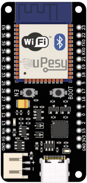
Pin Configuration
The ESP32 has a variety of pins for different functionalities. Below is a summary of the pin configuration:
| Pin Name | Functionality | Description |
|---|---|---|
| GPIO0 | General Purpose I/O, Boot Mode Select | Used for boot mode selection |
| GPIO2 | General Purpose I/O, ADC, Touch | Can be used as ADC or capacitive touch |
| GPIO12 | General Purpose I/O, ADC, Touch | ADC input, touch sensor |
| GPIO13 | General Purpose I/O, ADC, Touch | ADC input, touch sensor |
| GPIO15 | General Purpose I/O, ADC, Touch | ADC input, touch sensor |
| GPIO16 | General Purpose I/O | Used for general-purpose applications |
| GPIO17 | General Purpose I/O | Used for general-purpose applications |
| EN | Enable Pin | Resets the chip when pulled low |
| VIN | Power Input | Connect to 5V power supply |
| GND | Ground | Connect to ground |
Note: Not all GPIO pins support all functions simultaneously. Refer to the ESP32 datasheet for detailed pin multiplexing information.
Usage Instructions
The ESP32 can be programmed using the Arduino IDE, MicroPython, or the ESP-IDF framework. Below are the steps to use the ESP32 in a circuit and program it using the Arduino IDE.
Connecting the ESP32
- Power Supply: Connect the VIN pin to a 5V power source and GND to ground.
- USB Connection: Use a micro-USB cable to connect the ESP32 to your computer for programming.
- GPIO Pins: Connect peripherals (e.g., sensors, LEDs) to the GPIO pins as needed.
- Boot Mode: Hold the BOOT button while pressing the EN button to enter bootloader mode.
Programming the ESP32 with Arduino IDE
- Install the ESP32 board package in the Arduino IDE:
- Go to File > Preferences and add the following URL to the "Additional Board Manager URLs" field:
https://dl.espressif.com/dl/package_esp32_index.json - Open Tools > Board > Boards Manager, search for "ESP32," and install the package.
- Go to File > Preferences and add the following URL to the "Additional Board Manager URLs" field:
- Select the ESP32 board from Tools > Board.
- Write your code and upload it to the ESP32.
Example Code: Blinking an LED
The following example demonstrates how to blink an LED connected to GPIO2.
// Define the GPIO pin where the LED is connected
#define LED_PIN 2

void setup() {
  // Set the LED pin as an output
  pinMode(LED_PIN, OUTPUT);
}

void loop() {
  // Turn the LED on
  digitalWrite(LED_PIN, HIGH);
  delay(1000); // Wait for 1 second

  // Turn the LED off
  digitalWrite(LED_PIN, LOW);
  delay(1000); // Wait for 1 second
}
Best Practices
- Use a level shifter when interfacing the ESP32 with 5V logic devices, as its GPIO pins are not 5V tolerant.
- Avoid using GPIO6-GPIO11 for general-purpose tasks, as these are connected to the internal flash memory.
- Use decoupling capacitors near the power pins to ensure stable operation.
Troubleshooting and FAQs
Common Issues
ESP32 Not Detected by Computer
- Ensure the correct USB driver is installed for the ESP32.
- Check the USB cable for damage or try a different cable.
Upload Fails with "Failed to Connect" Error
- Hold the BOOT button while uploading the code.
- Verify the correct COM port is selected in the Arduino IDE.
Wi-Fi Connection Issues
- Double-check the SSID and password in your code.
- Ensure the Wi-Fi network is operating on the 2.4 GHz band (ESP32 does not support 5 GHz).
Random Resets or Instability
- Check the power supply for sufficient current (at least 500 mA).
- Add capacitors to stabilize the power supply.
FAQs
Q: Can the ESP32 operate on battery power?
A: Yes, the ESP32 can be powered by a battery. Use a 3.7V LiPo battery with a voltage regulator to provide 3.3V.
Q: How do I use Bluetooth on the ESP32?
A: The ESP32 supports both Bluetooth Classic and BLE. Use the BluetoothSerial library for Bluetooth Classic or the BLE library for BLE.
Q: Can I use the ESP32 with MicroPython?
A: Yes, the ESP32 supports MicroPython. Flash the MicroPython firmware to the ESP32 and use a Python IDE like Thonny to program it.
Q: What is the maximum range of the ESP32's Wi-Fi?
A: The range depends on the environment but typically extends up to 100 meters in open spaces.
By following this documentation, you can effectively use the ESP32 in your projects and troubleshoot common issues.