How to Use Arduino UNO R4 WiFi: Examples, Pinouts, and Specs
Introduction
The Arduino UNO R4 WiFi is a microcontroller board based on the ATmega328P, enhanced with built-in WiFi capabilities. This feature makes it an excellent choice for projects requiring internet connectivity, such as IoT (Internet of Things) applications, smart home devices, and remote monitoring systems. The board retains the simplicity and versatility of the classic Arduino UNO while adding modern connectivity options, making it suitable for both beginners and advanced users.
Explore Projects Built with Arduino UNO R4 WiFi

Explore Projects Built with Arduino UNO R4 WiFi
Common Applications and Use Cases
- IoT projects, such as smart sensors and connected devices
- Home automation systems
- Remote data logging and monitoring
- Wireless control of devices
- Educational projects involving internet-connected systems
Technical Specifications
Below are the key technical details of the Arduino UNO R4 WiFi:
| Specification | Details |
|---|---|
| Microcontroller | ATmega328P |
| Operating Voltage | 5V |
| Input Voltage (recommended) | 7-12V |
| Input Voltage (limit) | 6-20V |
| Digital I/O Pins | 14 (6 PWM outputs) |
| Analog Input Pins | 6 |
| Flash Memory | 32 KB (0.5 KB used by bootloader) |
| SRAM | 2 KB |
| EEPROM | 1 KB |
| Clock Speed | 16 MHz |
| WiFi Module | Integrated (based on ESP32-S3 or similar) |
| Communication Interfaces | UART, SPI, I2C |
| USB Connector | USB-C |
| Dimensions | 68.6 mm x 53.4 mm |
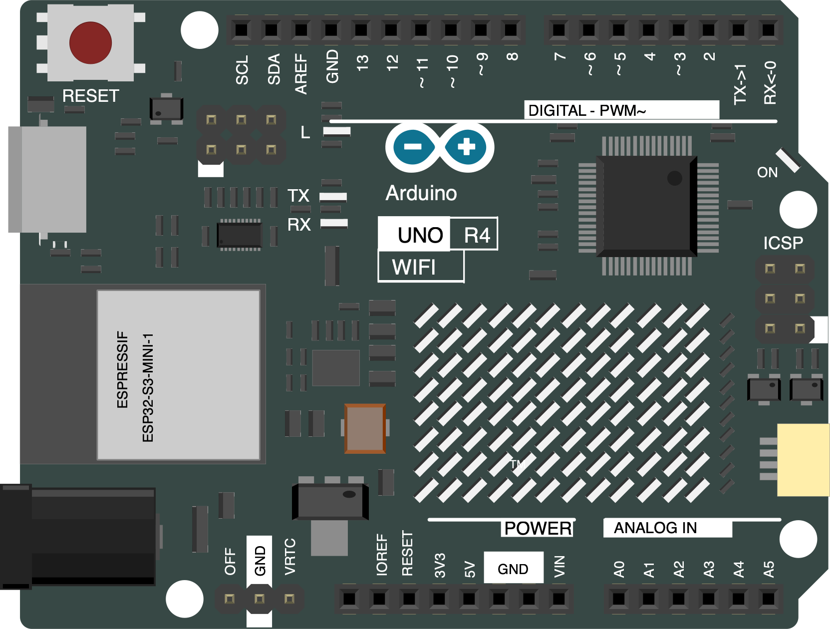
Pin Configuration and Descriptions
The Arduino UNO R4 WiFi features a standard pinout similar to the classic Arduino UNO, with additional functionality for WiFi connectivity. Below is the pin configuration:
| Pin | Type | Description |
|---|---|---|
| 0 (RX) | Digital I/O | UART Receive (Serial Communication) |
| 1 (TX) | Digital I/O | UART Transmit (Serial Communication) |
| 2-13 | Digital I/O | General-purpose digital input/output pins |
| 3, 5, 6, 9, 10, 11 | PWM | PWM-enabled digital pins |
| A0-A5 | Analog Input | Analog input pins (10-bit resolution) |
| GND | Power | Ground |
| 5V | Power | Regulated 5V output |
| 3.3V | Power | Regulated 3.3V output |
| VIN | Power | Input voltage to the board |
| RESET | Reset | Resets the microcontroller |
| WiFi TX | Communication | Transmit pin for WiFi module |
| WiFi RX | Communication | Receive pin for WiFi module |
Usage Instructions
How to Use the Arduino UNO R4 WiFi in a Circuit
Powering the Board:
- Use a USB-C cable to connect the board to your computer or a USB power source.
- Alternatively, supply 7-12V to the VIN pin for external power.
Programming the Board:
- Install the Arduino IDE from the official Arduino website.
- Select "Arduino UNO R4 WiFi" as the board in the Tools menu.
- Connect the board via USB-C and upload your sketch.
Using WiFi:
- Include the
WiFi.hlibrary in your sketch to enable WiFi functionality. - Configure the WiFi settings (SSID and password) in your code.
- Include the
Example Code for WiFi Connectivity
Below is an example sketch to connect the Arduino UNO R4 WiFi to a network and print the IP address:
#include <WiFi.h> // Include the WiFi library

const char* ssid = "YourNetworkSSID";     // Replace with your WiFi network name
const char* password = "YourNetworkPass"; // Replace with your WiFi password

void setup() {
  Serial.begin(9600); // Start serial communication at 9600 baud
  Serial.println("Connecting to WiFi...");

  WiFi.begin(ssid, password); // Connect to the WiFi network

  while (WiFi.status() != WL_CONNECTED) {
    delay(1000); // Wait for connection
    Serial.print(".");
  }

  Serial.println("\nConnected to WiFi!");
  Serial.print("IP Address: ");
  Serial.println(WiFi.localIP()); // Print the device's IP address
}

void loop() {
  // Add your main code here
}
Important Considerations and Best Practices
- Ensure the power supply voltage does not exceed the recommended range to avoid damaging the board.
- Use proper pull-up or pull-down resistors for input pins if required.
- Avoid placing the board near sources of electromagnetic interference, which may affect WiFi performance.
- Update the firmware of the WiFi module if necessary to ensure compatibility with the latest features.
Troubleshooting and FAQs
Common Issues and Solutions
The board is not detected by the Arduino IDE:
- Ensure the correct board and port are selected in the Tools menu.
- Check the USB-C cable for data transfer capability (some cables are power-only).
WiFi connection fails:
- Double-check the SSID and password in your sketch.
- Ensure the WiFi network is within range and not using unsupported security protocols.
Sketch upload fails:
- Press and hold the RESET button while uploading the sketch.
- Verify that no other application is using the COM port.
FAQs
Q: Can I use the Arduino UNO R4 WiFi with existing Arduino shields?
A: Yes, the board is compatible with most Arduino UNO shields, but ensure the shield does not interfere with the WiFi module.
Q: What is the range of the WiFi module?
A: The range depends on environmental factors but typically covers 30-50 meters indoors and up to 100 meters outdoors.
Q: How do I update the WiFi module firmware?
A: Use the Arduino IDE or the official Arduino firmware updater tool to update the firmware.
Q: Can I power the board using batteries?
A: Yes, you can use a battery pack that provides 7-12V to the VIN pin or a 5V regulated source to the 5V pin.
This documentation provides a comprehensive guide to using the Arduino UNO R4 WiFi, ensuring a smooth experience for your projects.