How to Use XL4016: Examples, Pinouts, and Specs
Introduction
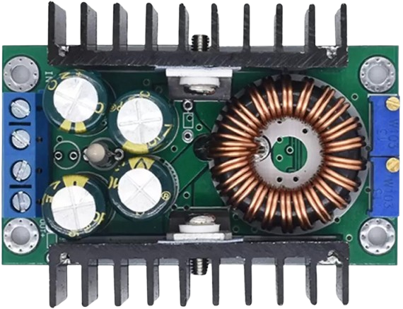
The XL4016 is a high-performance step-down (buck) voltage regulator designed to efficiently convert a higher input voltage to a lower output voltage. With its ability to handle up to 8A of output current, the XL4016 is ideal for applications requiring high power and efficiency. It is widely used in power supply circuits, battery chargers, LED drivers, and other electronic projects where stable voltage regulation is essential.
Explore Projects Built with XL4016


Explore Projects Built with XL4016
Common Applications:
- Adjustable DC power supplies
- Battery charging circuits
- LED lighting systems
- Motor speed controllers
- Embedded systems requiring regulated power
Technical Specifications
The XL4016 is a robust and versatile component with the following key specifications:
| Parameter | Value |
|---|---|
| Input Voltage Range | 5V to 40V |
| Output Voltage Range | 1.25V to 36V (adjustable) |
| Maximum Output Current | 8A (with proper heat dissipation) |
| Efficiency | Up to 95% |
| Switching Frequency | 180 kHz |
| Operating Temperature | -40°C to +85°C |
| Dimensions | Typically 60mm x 50mm x 20mm |
Pin Configuration and Descriptions
The XL4016 module typically comes with the following pinouts:
| Pin Name | Description |
|---|---|
| VIN | Input voltage pin. Connect the higher input voltage (5V to 40V). |
| VOUT | Output voltage pin. Provides the regulated lower voltage (1.25V to 36V). |
| GND | Ground pin. Common ground for input and output. |
| ADJ | Adjustment pin. Used to set the output voltage via a potentiometer or resistor. |
Usage Instructions
How to Use the XL4016 in a Circuit
Connect the Input Voltage (VIN):
- Attach the positive terminal of the input power source to the VIN pin.
- Connect the negative terminal of the input power source to the GND pin.
Set the Output Voltage:
- Use the onboard potentiometer (or an external resistor network) to adjust the output voltage.
- Measure the output voltage across the VOUT and GND pins using a multimeter while adjusting.
Connect the Load:
- Attach the positive terminal of your load to the VOUT pin.
- Connect the negative terminal of your load to the GND pin.
Ensure Proper Heat Dissipation:
- For high-current applications, attach a heatsink to the XL4016 module to prevent overheating.
- Ensure adequate ventilation around the module.
Power On:
- Once all connections are secure, power on the input source and verify the output voltage.
Important Considerations and Best Practices
- Input Voltage: Ensure the input voltage is at least 1.5V higher than the desired output voltage for proper regulation.
- Current Limitation: Do not exceed the 8A maximum output current. Use a heatsink and cooling fan for high-power applications.
- Polarity Protection: Double-check the polarity of the input and output connections to avoid damage.
- Ripple Reduction: Add input and output capacitors (e.g., 100µF electrolytic capacitors) to reduce voltage ripple.
Example: Using XL4016 with Arduino UNO
The XL4016 can be used to power an Arduino UNO by stepping down a higher voltage (e.g., 12V) to 5V. Below is an example circuit and code:
Circuit:
- Connect a 12V DC power source to the VIN and GND pins of the XL4016.
- Adjust the output voltage to 5V using the potentiometer.
- Connect the VOUT pin of the XL4016 to the 5V pin of the Arduino UNO.
- Connect the GND pin of the XL4016 to the GND pin of the Arduino UNO.
Code:
// Example code for Arduino UNO powered by XL4016
// This code blinks an LED connected to pin 13

void setup() {
  pinMode(13, OUTPUT); // Set pin 13 as an output pin
}

void loop() {
  digitalWrite(13, HIGH); // Turn the LED on
  delay(1000);            // Wait for 1 second
  digitalWrite(13, LOW);  // Turn the LED off
  delay(1000);            // Wait for 1 second
}
Troubleshooting and FAQs
Common Issues and Solutions
No Output Voltage:
- Cause: Incorrect input connections or insufficient input voltage.
- Solution: Verify the input voltage is within the 5V to 40V range and check the polarity.
Overheating:
- Cause: High output current without proper heat dissipation.
- Solution: Attach a heatsink and ensure adequate ventilation.
Voltage Fluctuations:
- Cause: Insufficient filtering or unstable input voltage.
- Solution: Add input and output capacitors to reduce ripple and stabilize the voltage.
Output Voltage Not Adjustable:
- Cause: Faulty potentiometer or incorrect adjustment.
- Solution: Replace the potentiometer or check the adjustment process.
FAQs
Q1: Can the XL4016 be used to charge batteries?
Yes, the XL4016 can be used for battery charging applications. However, ensure the output voltage and current are set according to the battery's specifications.
Q2: What is the maximum power output of the XL4016?
The maximum power output depends on the input voltage and current. For example, at 36V input and 8A output, the power output is approximately 288W.
Q3: Can the XL4016 handle reverse polarity?
No, the XL4016 does not have built-in reverse polarity protection. Always double-check the polarity of your connections.
Q4: How can I reduce noise in the output voltage?
Adding low ESR capacitors (e.g., 100µF or higher) to the input and output terminals can help reduce noise and ripple.
By following this documentation, you can effectively use the XL4016 in your electronic projects and ensure reliable performance.