How to Use gear motor: Examples, Pinouts, and Specs
Introduction
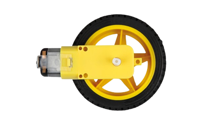
A gear motor is an electric motor integrated with a gear system to reduce speed and increase torque. This combination makes it ideal for applications requiring high torque at low speeds. Gear motors are widely used in robotics, conveyor systems, industrial machinery, and automotive applications. They are particularly valued for their ability to deliver precise motion control and power efficiency.
Manufacturer: Rajesh Shah
Part ID: motor
Explore Projects Built with gear motor


Explore Projects Built with gear motor
Technical Specifications
Below are the key technical details for the gear motor:
| Parameter | Value |
|---|---|
| Operating Voltage | 6V - 12V |
| Rated Torque | 5 kg·cm - 20 kg·cm (varies by model) |
| No-Load Speed | 30 RPM - 300 RPM |
| Gear Ratio | 10:1 to 100:1 (varies by model) |
| Current Consumption | 100 mA - 1.5 A (depending on load) |
| Shaft Diameter | 6 mm |
| Motor Type | DC Brushed Motor |
| Operating Temperature | -10°C to 50°C |
| Weight | 150 g - 500 g (varies by model) |
Pin Configuration and Descriptions
The gear motor typically has two terminals for electrical connections. The table below describes the pin configuration:
| Pin/Terminal | Description |
|---|---|
| Terminal 1 | Positive terminal for power supply (VCC) |
| Terminal 2 | Negative terminal for power supply (GND) |
Note: The polarity of the terminals determines the direction of rotation. Reversing the polarity will reverse the motor's direction.
Usage Instructions
How to Use the Gear Motor in a Circuit
- Power Supply: Connect the gear motor to a DC power supply within the specified voltage range (6V - 12V). Ensure the power supply can provide sufficient current for the motor's operation.
- Motor Driver: Use a motor driver (e.g., L298N or L293D) to control the motor's speed and direction. Directly connecting the motor to a microcontroller is not recommended due to high current requirements.
- Polarity Control: To change the direction of rotation, reverse the polarity of the power supply or use an H-bridge circuit.
- Mounting: Secure the motor using screws or brackets to prevent vibration during operation.
Important Considerations and Best Practices
- Avoid Overloading: Do not exceed the rated torque to prevent damage to the motor or gear system.
- Heat Dissipation: Ensure proper ventilation to avoid overheating, especially during prolonged use.
- Noise Reduction: Use rubber mounts or dampers to minimize noise and vibration.
- Power Supply: Use a regulated power supply to avoid voltage spikes that could damage the motor.
- Lubrication: Periodically check and lubricate the gear system to maintain efficiency and reduce wear.
Example: Controlling a Gear Motor with Arduino UNO
Below is an example of how to control a gear motor using an Arduino UNO and an L298N motor driver:
// Include necessary pins for motor control
const int ENA = 9;  // PWM pin for speed control
const int IN1 = 8;  // Direction control pin 1
const int IN2 = 7;  // Direction control pin 2

void setup() {
  // Set motor control pins as outputs
  pinMode(ENA, OUTPUT);
  pinMode(IN1, OUTPUT);
  pinMode(IN2, OUTPUT);
}

void loop() {
  // Rotate motor in one direction
  digitalWrite(IN1, HIGH);  // Set IN1 high
  digitalWrite(IN2, LOW);   // Set IN2 low
  analogWrite(ENA, 150);    // Set speed (0-255)

  delay(3000);  // Run for 3 seconds

  // Stop the motor
  analogWrite(ENA, 0);  // Set speed to 0
  delay(1000);          // Wait for 1 second

  // Rotate motor in the opposite direction
  digitalWrite(IN1, LOW);   // Set IN1 low
  digitalWrite(IN2, HIGH);  // Set IN2 high
  analogWrite(ENA, 150);    // Set speed (0-255)

  delay(3000);  // Run for 3 seconds

  // Stop the motor
  analogWrite(ENA, 0);  // Set speed to 0
  delay(1000);          // Wait for 1 second
}
Explanation:
- The
ENApin controls the motor's speed using PWM signals. - The
IN1andIN2pins control the motor's direction. - The motor rotates in one direction for 3 seconds, stops for 1 second, and then rotates in the opposite direction for 3 seconds.
Troubleshooting and FAQs
Common Issues and Solutions
Motor Does Not Rotate:
- Cause: Insufficient power supply or loose connections.
- Solution: Check the power supply voltage and current. Ensure all connections are secure.
Motor Overheats:
- Cause: Overloading or prolonged operation at high torque.
- Solution: Reduce the load or allow the motor to cool down periodically.
Excessive Noise or Vibration:
- Cause: Loose mounting or worn-out gears.
- Solution: Tighten the mounting screws and inspect the gear system for wear.
Motor Rotates in the Wrong Direction:
- Cause: Incorrect polarity or wiring.
- Solution: Reverse the polarity of the power supply or swap the IN1 and IN2 connections.
FAQs
Q1: Can I connect the gear motor directly to an Arduino?
A1: No, the gear motor requires more current than the Arduino can supply. Use a motor driver or relay module.
Q2: How do I calculate the required torque for my application?
A2: Determine the load's weight and the distance from the motor shaft. Use the formula:
Torque (kg·cm) = Load (kg) × Distance (cm).
Q3: Can I use the gear motor with a battery?
A3: Yes, ensure the battery voltage matches the motor's operating range and can supply sufficient current.
Q4: How do I reduce the motor's speed further?
A4: Use a motor driver with PWM control or select a gear motor with a higher gear ratio.
This concludes the documentation for the gear motor. For further assistance, refer to the manufacturer's datasheet or contact technical support.