How to Use ItsyBitsy ESP32: Examples, Pinouts, and Specs
Introduction
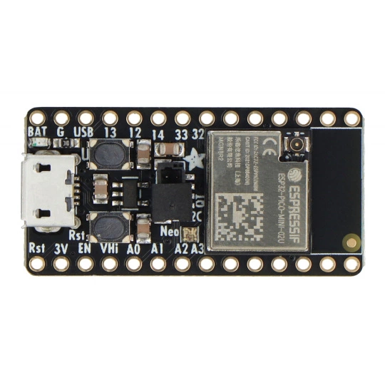
The ItsyBitsy ESP32 is a compact microcontroller board developed by Adafruit, featuring the powerful ESP32-PICO-MINI-02 module. This board is designed for Internet of Things (IoT) applications, offering built-in Wi-Fi and Bluetooth capabilities. Its small form factor makes it ideal for projects where space is limited, while still providing robust wireless connectivity and processing power.
Explore Projects Built with ItsyBitsy ESP32


Explore Projects Built with ItsyBitsy ESP32
Common Applications and Use Cases
- IoT devices and smart home automation
- Wireless sensor networks
- Wearable technology
- Robotics and remote control systems
- Data logging and real-time monitoring
- Prototyping and educational projects
Technical Specifications
The following table outlines the key technical details of the ItsyBitsy ESP32:
| Specification | Details |
|---|---|
| Microcontroller | ESP32-PICO-MINI-02 |
| Processor | Dual-core Xtensa® 32-bit LX6 microprocessor |
| Clock Speed | Up to 240 MHz |
| Flash Memory | 4 MB |
| SRAM | 520 KB |
| Wireless Connectivity | Wi-Fi (802.11 b/g/n) and Bluetooth (Classic + BLE) |
| Operating Voltage | 3.3V |
| Input Voltage Range | 3.3V to 6V (via USB or external power) |
| GPIO Pins | 23 (including ADC, DAC, I2C, SPI, UART, PWM) |
| Analog Inputs | 6 ADC channels (12-bit resolution) |
| Digital Outputs | PWM support on multiple pins |
| Dimensions | 35.9 mm x 17.8 mm x 4.6 mm |
| Weight | ~3 grams |
Pin Configuration and Descriptions
The ItsyBitsy ESP32 features a total of 23 GPIO pins, with multiple functions. Below is the pinout description:
| Pin | Function | Description |
|---|---|---|
| VIN | Power Input | Accepts 3.3V to 6V input for powering the board. |
| 3V3 | 3.3V Output | Regulated 3.3V output for external components. |
| GND | Ground | Common ground for the circuit. |
| GPIO0 | Digital I/O, ADC, Touch | General-purpose I/O, analog input, or capacitive touch sensing. |
| GPIO1 | UART TX | Serial communication transmit pin. |
| GPIO3 | UART RX | Serial communication receive pin. |
| GPIO4 | Digital I/O, ADC, PWM | General-purpose I/O, analog input, or PWM output. |
| GPIO5 | Digital I/O, ADC, PWM | General-purpose I/O, analog input, or PWM output. |
| GPIO12 | Digital I/O, ADC, DAC | General-purpose I/O, analog input, or digital-to-analog conversion. |
| GPIO13 | Digital I/O, ADC, PWM | General-purpose I/O, analog input, or PWM output. |
| GPIO14 | Digital I/O, ADC, PWM | General-purpose I/O, analog input, or PWM output. |
| GPIO15 | Digital I/O, ADC, PWM | General-purpose I/O, analog input, or PWM output. |
| GPIO16 | Digital I/O | General-purpose I/O. |
| GPIO17 | Digital I/O | General-purpose I/O. |
| GPIO18 | SPI SCK | Serial Peripheral Interface clock pin. |
| GPIO19 | SPI MISO | Serial Peripheral Interface Master-In-Slave-Out pin. |
| GPIO21 | I2C SDA | I2C data line. |
| GPIO22 | I2C SCL | I2C clock line. |
| GPIO23 | SPI MOSI | Serial Peripheral Interface Master-Out-Slave-In pin. |
| EN | Enable | Enable pin to reset or wake the board. |
| RST | Reset | Reset pin to restart the microcontroller. |
Usage Instructions
How to Use the ItsyBitsy ESP32 in a Circuit
Powering the Board:
- Connect the board to a USB power source or provide an external voltage (3.3V to 6V) to the VIN pin.
- Ensure the power supply is stable to avoid damaging the board.
Programming the Board:
- Install the ESP32 board support package in the Arduino IDE or use the ESP-IDF framework for advanced development.
- Connect the board to your computer via a USB cable.
- Select the correct board (e.g., "Adafruit ItsyBitsy ESP32") and port in the Arduino IDE.
- Write your code and upload it to the board.
Connecting Peripherals:
- Use the GPIO pins to connect sensors, actuators, or other peripherals.
- Refer to the pin configuration table to ensure proper connections.
Wireless Connectivity:
- Use the built-in Wi-Fi and Bluetooth features for wireless communication.
- Configure the network settings in your code to connect to a Wi-Fi network or pair with Bluetooth devices.
Important Considerations and Best Practices
- Avoid applying voltages higher than 3.3V to the GPIO pins to prevent damage.
- Use level shifters if interfacing with 5V logic devices.
- Ensure proper grounding for stable operation.
- Use decoupling capacitors near power pins to reduce noise in the circuit.
- When using Wi-Fi, ensure the antenna area is not obstructed for optimal signal strength.
Example Code for Arduino UNO Integration
Below is an example of using the ItsyBitsy ESP32 to connect to a Wi-Fi network and send data to a server:
#include <WiFi.h>

// Replace with your network credentials
const char* ssid = "Your_SSID";
const char* password = "Your_PASSWORD";

void setup() {
  Serial.begin(115200); // Initialize serial communication at 115200 baud
  delay(1000);

  // Connect to Wi-Fi
  Serial.print("Connecting to Wi-Fi");
  WiFi.begin(ssid, password);
  while (WiFi.status() != WL_CONNECTED) {
    delay(500);
    Serial.print(".");
  }
  Serial.println("\nConnected to Wi-Fi!");
}

void loop() {
  // Example: Print the IP address
  Serial.print("IP Address: ");
  Serial.println(WiFi.localIP());
  delay(5000); // Wait for 5 seconds before repeating
}
Troubleshooting and FAQs
Common Issues and Solutions
Board Not Detected by Computer:
- Ensure the USB cable is functional and supports data transfer.
- Check if the correct drivers are installed for the ESP32.
Wi-Fi Connection Fails:
- Verify the SSID and password in your code.
- Ensure the Wi-Fi network is within range and not overloaded.
Program Upload Fails:
- Check if the correct board and port are selected in the Arduino IDE.
- Press and hold the "BOOT" button on the board while uploading the code.
GPIO Pins Not Working:
- Confirm the pin mode is correctly set in your code (e.g.,
pinMode(pin, OUTPUT)). - Check for short circuits or incorrect wiring.
- Confirm the pin mode is correctly set in your code (e.g.,
FAQs
Q: Can I power the ItsyBitsy ESP32 with a LiPo battery?
A: Yes, you can use a 3.7V LiPo battery connected to the VIN pin. Ensure the battery voltage does not exceed 6V.
Q: Does the board support deep sleep mode?
A: Yes, the ESP32 supports deep sleep mode for low-power applications. Use the esp_sleep_enable_* functions in your code to configure sleep modes.
Q: Can I use the ItsyBitsy ESP32 with MicroPython?
A: Yes, the board is compatible with MicroPython. Flash the MicroPython firmware to the board and use a Python IDE for development.
Q: How do I reset the board?
A: Press the "RST" button on the board to reset the microcontroller.