How to Use 5V 8 Channel Relay Module: Examples, Pinouts, and Specs
Introduction
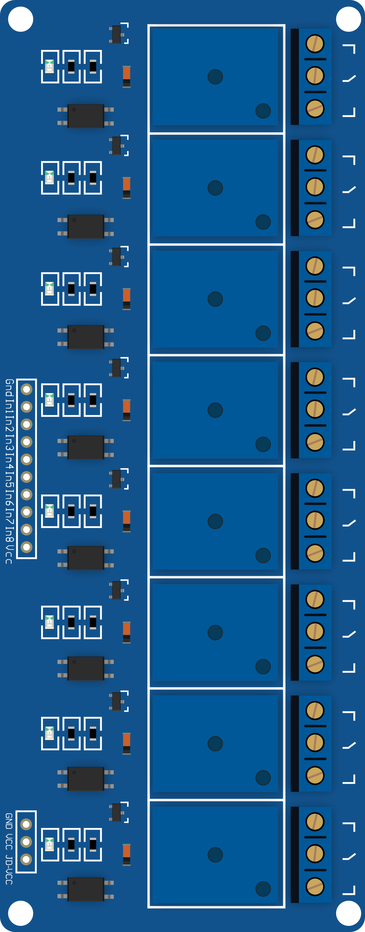
The 5V 8 Channel Relay Module is a versatile electronic component designed to control up to 8 devices using a 5V control signal. This module is commonly used for switching high voltage or high current loads, making it ideal for applications such as home automation, industrial control systems, and robotics. By using a low voltage control signal, the relay module can safely manage high power devices without direct electrical connection, ensuring both safety and efficiency.
Explore Projects Built with 5V 8 Channel Relay Module


Explore Projects Built with 5V 8 Channel Relay Module
Technical Specifications
Key Technical Details
| Parameter | Value |
|---|---|
| Operating Voltage | 5V DC |
| Trigger Voltage | 5V DC |
| Relay Channels | 8 |
| Max Switching Voltage (AC) | 250V AC |
| Max Switching Voltage (DC) | 30V DC |
| Max Switching Current | 10A |
| Relay Type | SPDT (Single Pole Double Throw) |
| Dimensions | 138mm x 56mm x 18mm |
Pin Configuration and Descriptions
Control Pins
| Pin Number | Pin Name | Description |
|---|---|---|
| 1 | IN1 | Control signal for Relay 1 (Active Low) |
| 2 | IN2 | Control signal for Relay 2 (Active Low) |
| 3 | IN3 | Control signal for Relay 3 (Active Low) |
| 4 | IN4 | Control signal for Relay 4 (Active Low) |
| 5 | IN5 | Control signal for Relay 5 (Active Low) |
| 6 | IN6 | Control signal for Relay 6 (Active Low) |
| 7 | IN7 | Control signal for Relay 7 (Active Low) |
| 8 | IN8 | Control signal for Relay 8 (Active Low) |
| 9 | GND | Ground |
| 10 | VCC | 5V Power Supply |
Relay Output Pins
Each relay channel has three output pins:
| Pin Name | Description |
|---|---|
| NO | Normally Open (connected when relay is activated) |
| COM | Common |
| NC | Normally Closed (connected when relay is not activated) |
Usage Instructions
How to Use the Component in a Circuit
- Power Supply: Connect the VCC pin to a 5V power supply and the GND pin to the ground of your circuit.
- Control Signals: Connect the control pins (IN1 to IN8) to the digital output pins of a microcontroller (e.g., Arduino UNO).
- Load Connections: Connect the devices you want to control to the relay output pins (NO, COM, NC) as per your requirement.
Example Circuit with Arduino UNO
/*
  Example code to control an 8 Channel Relay Module with Arduino UNO.
  This code will sequentially turn on each relay for 1 second and then turn it off.
*/

const int relayPins[8] = {2, 3, 4, 5, 6, 7, 8, 9}; // Define relay control pins

void setup() {
  // Initialize all relay pins as OUTPUT
  for (int i = 0; i < 8; i++) {
    pinMode(relayPins[i], OUTPUT);
    digitalWrite(relayPins[i], HIGH); // Ensure all relays are off initially
  }
}

void loop() {
  for (int i = 0; i < 8; i++) {
    digitalWrite(relayPins[i], LOW); // Turn on relay (active low)
    delay(1000); // Wait for 1 second
    digitalWrite(relayPins[i], HIGH); // Turn off relay
    delay(500); // Wait for 0.5 second before next relay
  }
}
Important Considerations and Best Practices
- Isolation: Ensure proper isolation between the low voltage control side and the high voltage load side to prevent damage and ensure safety.
- Power Supply: Use a stable 5V power supply to avoid malfunctioning of the relay module.
- Heat Dissipation: If switching high current loads, ensure adequate ventilation or heat sinks to prevent overheating.
- Debouncing: Implement debouncing in your control signals to avoid unintended relay activation due to noise.
Troubleshooting and FAQs
Common Issues Users Might Face
Relays Not Activating:
- Solution: Check the power supply voltage and ensure it is 5V. Verify that the control signals are correctly connected and are at the correct voltage level.
Relays Stuck in One State:
- Solution: Ensure that the control signals are properly toggling between HIGH and LOW states. Check for any short circuits or faulty connections.
Overheating:
- Solution: Ensure that the load current does not exceed the relay's maximum rating. Provide adequate cooling or ventilation.
FAQs
Can I use this relay module with a 3.3V microcontroller?
- Yes, but you will need a level shifter or transistor to step up the control signal to 5V.
What is the maximum load I can control with this relay module?
- Each relay can handle up to 10A at 250V AC or 30V DC.
Is it safe to switch high voltage loads with this module?
- Yes, as long as you ensure proper isolation and follow safety guidelines.
By following this documentation, users can effectively utilize the 5V 8 Channel Relay Module in their projects, ensuring both functionality and safety.