How to Use 2 gang 3 usb port : Examples, Pinouts, and Specs
Introduction
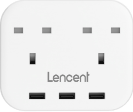
The 2 Gang 3 USB Port is a versatile wall-mounted power outlet that combines two standard AC power sockets (gangs) with three USB charging ports. This component is designed to provide a convenient solution for powering traditional electrical devices while simultaneously charging USB-powered gadgets such as smartphones, tablets, and other portable electronics.
Explore Projects Built with 2 gang 3 usb port


Explore Projects Built with 2 gang 3 usb port
Common Applications and Use Cases
- Residential and commercial wall outlets for combined AC and USB power needs.
- Charging stations in offices, hotels, and public spaces.
- Home automation setups where USB-powered devices are frequently used.
- Replacement for traditional wall sockets to modernize power access.
Technical Specifications
Key Technical Details
| Parameter | Specification |
|---|---|
| Input Voltage (AC) | 100-240V AC, 50/60Hz |
| Output Voltage (USB Ports) | 5V DC ± 5% |
| USB Output Current | 2.1A (max per port), 3.1A (total max) |
| Power Rating (AC Sockets) | 13A, 250V AC |
| USB Ports | 3 USB Type-A |
| Gang Type | 2 Gang (dual AC sockets) |
| Material | Fire-retardant polycarbonate |
| Certifications | CE, FCC, RoHS compliant |
Pin Configuration and Descriptions
AC Power Sockets
| Pin Name | Description |
|---|---|
| Live (L) | Connects to the live wire of the AC power supply. |
| Neutral (N) | Connects to the neutral wire of the AC power supply. |
| Earth (E) | Provides grounding for safety. |
USB Ports
| Pin Name | Description |
|---|---|
| V+ (5V) | Supplies 5V DC power to connected USB devices. |
| GND | Ground connection for USB devices. |
| D+ | Data line for USB communication (optional). |
| D- | Data line for USB communication (optional). |
Usage Instructions
How to Use the Component in a Circuit
Installation:
- Turn off the main power supply before installation.
- Connect the live (L), neutral (N), and earth (E) wires to the corresponding terminals on the back of the 2 Gang 3 USB Port.
- Secure the component into the wall box using screws and ensure it is flush with the wall surface.
Using the AC Sockets:
- Plug in standard electrical devices (e.g., lamps, appliances) into the two AC sockets.
- Ensure the total load does not exceed the rated 13A.
Using the USB Ports:
- Connect USB-powered devices directly to the USB ports using appropriate cables.
- The USB ports automatically adjust the output current based on the connected device's requirements.
Important Considerations and Best Practices
- Overload Protection: Do not exceed the maximum power rating of 13A for the AC sockets or 3.1A for the USB ports.
- Heat Management: Ensure proper ventilation around the component to prevent overheating.
- Compatibility: The USB ports are designed for 5V devices only. Do not connect devices requiring higher voltages.
- Safety: Always ensure the component is properly grounded to avoid electrical hazards.
Arduino UNO Integration
While the 2 Gang 3 USB Port is not directly programmable, it can be used to power an Arduino UNO via its USB ports. Below is an example of how to power an Arduino UNO using this component:
// Example: Powering Arduino UNO via USB port of 2 Gang 3 USB Port
// Connect the Arduino UNO to one of the USB ports using a USB cable.
// No additional code is required for power supply, as the USB port
// provides the necessary 5V DC power to the Arduino UNO.
Troubleshooting and FAQs
Common Issues and Solutions
| Issue | Possible Cause | Solution |
|---|---|---|
| USB ports not charging devices | Overloaded USB ports or faulty cable | Disconnect some devices or replace the cable. |
| AC sockets not providing power | Loose wiring or tripped circuit breaker | Check wiring and reset the breaker. |
| Overheating during use | Exceeding power rating or poor ventilation | Reduce load and ensure proper airflow. |
| Device charges slowly via USB | High power demand from connected devices | Use fewer devices or connect high-demand devices individually. |
FAQs
Can I use this component in outdoor installations?
- No, this component is designed for indoor use only. Use weatherproof outlets for outdoor applications.
What happens if I connect a device requiring more than 2.1A to a USB port?
- The USB port will limit the current to 2.1A, which may result in slower charging or no charging at all.
Is it safe to use all USB ports and AC sockets simultaneously?
- Yes, as long as the total load does not exceed the rated limits (13A for AC sockets and 3.1A for USB ports).
Can I replace the USB ports with USB-C ports?
- No, the component is not designed for user modifications. Altering it may void the warranty and compromise safety.
By following this documentation, users can safely and effectively utilize the 2 Gang 3 USB Port for their power and charging needs.