
How to Use USB Connectors: Examples, Pinouts, and Specs
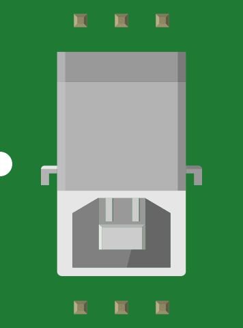
 Design with USB Connectors in Cirkit Designer
Introduction
USB connectors, manufactured by SparkFun (Part ID: PRT-00139), are standardized interfaces widely used for connecting electronic devices to computers, power sources, and other peripherals. These connectors facilitate data transfer, device communication, and power delivery, making them essential components in modern electronics.
Common applications include:
- Charging mobile devices, wearables, and other portable electronics
- Data transfer between computers and external devices (e.g., flash drives, external hard drives)
- Connecting peripherals such as keyboards, mice, and printers
- Powering embedded systems and development boards like Arduino
Explore Projects Built with USB Connectors
 Open Project in Cirkit Designer
 Open Project in Cirkit Designer
 Open Project in Cirkit Designer
 Open Project in Cirkit Designer
Explore Projects Built with USB Connectors
Open Project in Cirkit DesignerOpen Project in Cirkit DesignerOpen Project in Cirkit DesignerOpen Project in Cirkit DesignerTechnical Specifications
Below are the key technical details for SparkFun's USB connectors (PRT-00139):
General Specifications
- Connector Type: USB Type-A (Female)
- Mounting Style: Through-hole
- Voltage Rating: 5V DC (standard USB voltage)
- Current Rating: Up to 1.5A (depending on the connected device)
- Data Transfer Speed: Supports USB 2.0 (up to 480 Mbps)
- Material: Nickel-plated contacts for durability and reliable connections
- Operating Temperature: -20°C to 85°C
Pin Configuration and Descriptions
The USB Type-A connector has four pins, as detailed in the table below:
| Pin Number | Name | Description |
|---|---|---|
| 1 | VBUS | +5V power supply |
| 2 | D- | Data line for differential signaling (negative) |
| 3 | D+ | Data line for differential signaling (positive) |
| 4 | GND | Ground (0V reference) |
Usage Instructions
How to Use the USB Connector in a Circuit
Mounting the Connector:
- Solder the through-hole pins of the USB connector onto a PCB. Ensure proper alignment to avoid misconnection.
- Use a soldering iron with a fine tip for precise soldering, and avoid overheating the pins.
Connecting Power and Data Lines:
- Connect the VBUS pin to a regulated 5V power source.
- Connect the GND pin to the ground of your circuit.
- Use the D- and D+ pins for data communication. Ensure proper differential pair routing for high-speed data transfer.
Testing the Connection:
- After soldering, verify the connections using a multimeter to ensure there are no shorts or open circuits.
- Plug in a USB cable and test the functionality with the intended device.
Important Considerations and Best Practices
- Power Supply: Ensure the power source connected to the VBUS pin can supply sufficient current for the connected device.
- Signal Integrity: For high-speed data transfer, keep the D- and D+ traces as short and parallel as possible to minimize signal interference.
- Overcurrent Protection: Use a fuse or current-limiting circuit to protect the USB connector and connected devices from overcurrent conditions.
- ESD Protection: Add ESD protection diodes to the data lines to safeguard against electrostatic discharge.
Example: Connecting to an Arduino UNO
The USB connector can be used to power an Arduino UNO or facilitate serial communication. Below is an example of Arduino code to read data sent via USB:
// This code reads data sent to the Arduino via USB and echoes it back.
// Open the Serial Monitor in the Arduino IDE to test this functionality.

void setup() {
  Serial.begin(9600); // Initialize serial communication at 9600 baud
  while (!Serial) {
    // Wait for the serial port to connect (only needed for native USB boards)
  }
  Serial.println("USB Communication Initialized");
}

void loop() {
  if (Serial.available() > 0) {
    // Check if data is available to read
    char receivedChar = Serial.read(); // Read the incoming character
    Serial.print("You sent: ");
    Serial.println(receivedChar); // Echo the received character back
  }
}
Troubleshooting and FAQs
Common Issues
No Power to the Connected Device:
- Cause: Improper soldering or loose connections.
- Solution: Check the VBUS and GND connections with a multimeter. Resolder if necessary.
Data Transfer Fails:
- Cause: Incorrect wiring of D- and D+ pins or excessive noise on the data lines.
- Solution: Verify the D- and D+ connections. Ensure the traces are short and parallel.
Overheating of the Connector:
- Cause: Overcurrent or short circuit.
- Solution: Add a current-limiting circuit or fuse. Check for shorts between pins.
Device Not Recognized by the Computer:
- Cause: Faulty USB cable or incorrect pin connections.
- Solution: Test with a different USB cable. Verify the pin connections.
FAQs
Q1: Can this USB connector be used for USB 3.0 applications?
A1: No, this connector supports USB 2.0 only. For USB 3.0, a different connector with additional pins is required.
Q2: What is the maximum current this connector can handle?
A2: The connector can handle up to 1.5A, but ensure the connected device does not exceed this limit.
Q3: Can I use this connector for charging devices?
A3: Yes, it can be used for charging devices that require 5V and up to 1.5A.
Q4: Is this connector compatible with microcontrollers other than Arduino?
A4: Yes, it can be used with any microcontroller that supports USB communication or requires a 5V power supply.
By following this documentation, users can effectively integrate SparkFun's USB connectors (PRT-00139) into their projects for reliable power and data connections.