How to Use rtc: Examples, Pinouts, and Specs
Introduction
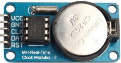
A Real-Time Clock (RTC) is a timekeeping device designed to maintain accurate time and date information, even when the main power supply is disconnected. This is achieved through the use of a small backup battery. Manufactured by RCT, the RTC (Part ID: RTC) is a versatile and reliable component widely used in various applications requiring precise timekeeping.
Explore Projects Built with rtc
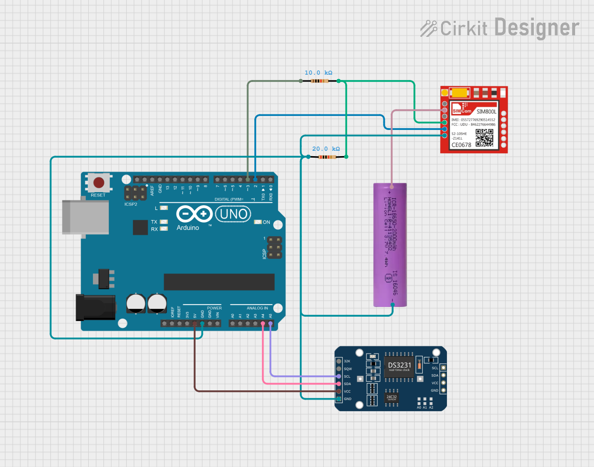
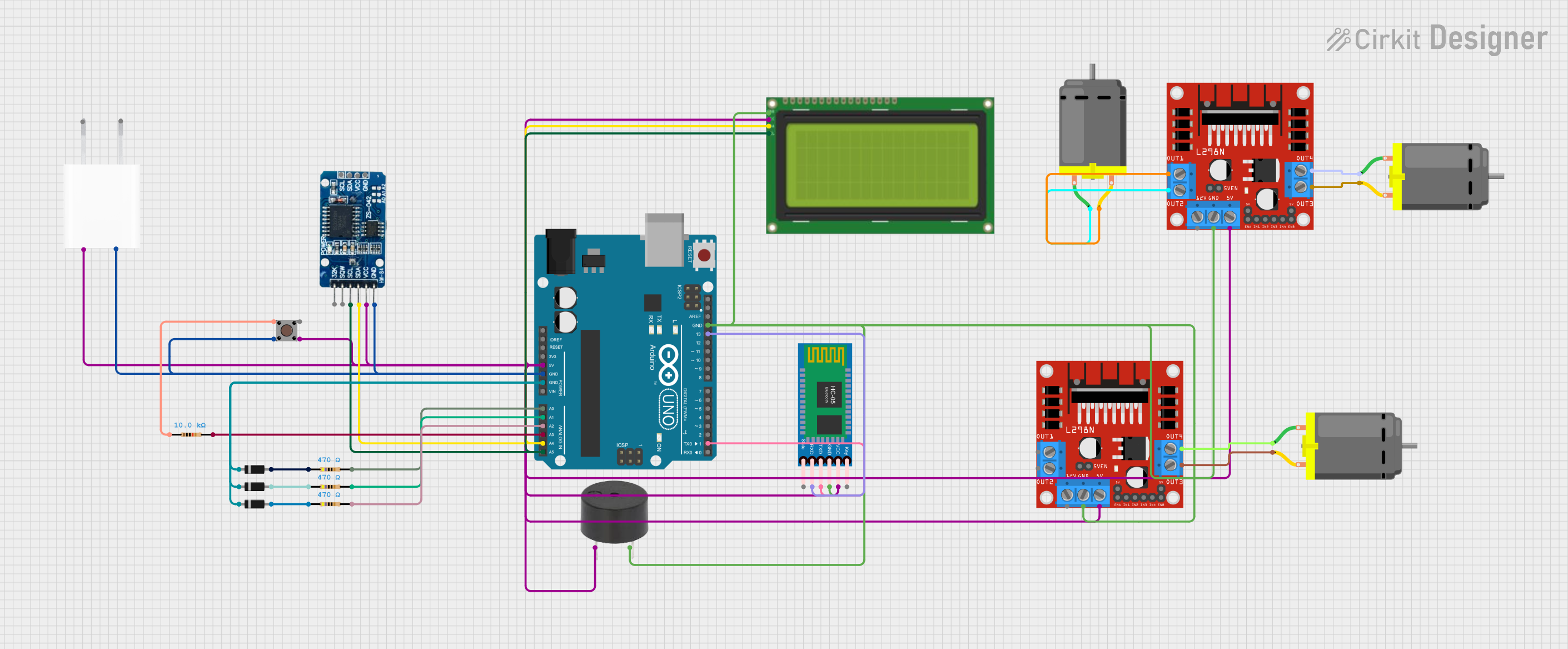

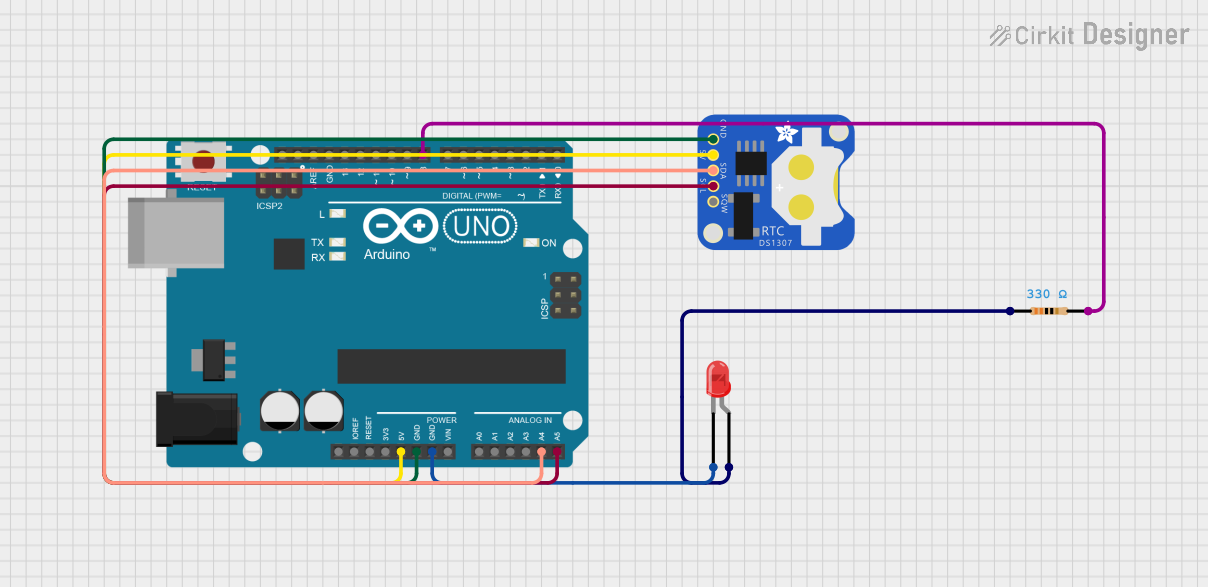
Explore Projects Built with rtc
Common Applications and Use Cases
- Digital clocks and watches
- Data logging systems
- Scheduling and automation systems
- Embedded systems requiring time-stamped data
- IoT devices for time synchronization
- Alarm systems and timers
Technical Specifications
The RCT RTC is designed to provide accurate and reliable timekeeping with minimal power consumption. Below are the key technical details and pin configuration:
Key Technical Details
| Parameter | Value |
|---|---|
| Operating Voltage | 2.0V to 5.5V |
| Backup Battery Voltage | 2.0V to 3.6V |
| Current Consumption | < 1 µA (in backup mode) |
| Timekeeping Accuracy | ±2 ppm at 25°C |
| Operating Temperature | -40°C to +85°C |
| Communication Interface | I2C (Inter-Integrated Circuit) |
| Clock Format | 24-hour or 12-hour with AM/PM |
| Timekeeping Features | Seconds, Minutes, Hours, Day, |
| Date, Month, Year |
Pin Configuration and Descriptions
The RTC module typically comes with 8 pins. Below is the pinout and description:
| Pin Number | Pin Name | Description |
|---|---|---|
| 1 | VCC | Power supply input (2.0V to 5.5V) |
| 2 | GND | Ground connection |
| 3 | SDA | Serial Data Line for I2C communication |
| 4 | SCL | Serial Clock Line for I2C communication |
| 5 | SQW/OUT | Square Wave/Output pin for alarms or interrupts |
| 6 | VBAT | Backup battery input (2.0V to 3.6V) |
| 7 | NC | Not connected (reserved for future use) |
| 8 | NC | Not connected (reserved for future use) |
Usage Instructions
How to Use the RTC in a Circuit
- Power Supply: Connect the VCC pin to a regulated power source (2.0V to 5.5V) and the GND pin to the ground.
- Backup Battery: Attach a 3V coin cell battery to the VBAT pin to ensure timekeeping during power outages.
- I2C Communication: Connect the SDA and SCL pins to the corresponding I2C pins on your microcontroller (e.g., Arduino UNO).
- Optional Output: Use the SQW/OUT pin for generating square wave signals or alarms, if required.
Important Considerations and Best Practices
- Use pull-up resistors (typically 4.7kΩ) on the SDA and SCL lines for proper I2C communication.
- Ensure the backup battery is installed correctly to maintain timekeeping during power loss.
- Avoid exposing the RTC to extreme temperatures beyond its operating range (-40°C to +85°C).
- Use decoupling capacitors (e.g., 0.1 µF) near the VCC pin to reduce noise and improve stability.
Example Code for Arduino UNO
Below is an example of how to interface the RTC with an Arduino UNO using the Wire library:
#include <Wire.h> // Include the Wire library for I2C communication

#define RTC_ADDRESS 0x68 // I2C address of the RTC module

void setup() {
  Wire.begin(); // Initialize I2C communication
  Serial.begin(9600); // Start serial communication for debugging

  // Set the time and date (e.g., 12:30:45 on 25th October 2023)
  Wire.beginTransmission(RTC_ADDRESS);
  Wire.write(0x00); // Set register pointer to seconds
  Wire.write(0x00); // Seconds (00)
  Wire.write(0x30); // Minutes (30)
  Wire.write(0x12); // Hours (12, 24-hour format)
  Wire.write(0x03); // Day of the week (e.g., 3 = Wednesday)
  Wire.write(0x25); // Date (25)
  Wire.write(0x10); // Month (10 = October)
  Wire.write(0x23); // Year (23 = 2023)
  Wire.endTransmission();
}

void loop() {
  Wire.beginTransmission(RTC_ADDRESS);
  Wire.write(0x00); // Set register pointer to seconds
  Wire.endTransmission();

  Wire.requestFrom(RTC_ADDRESS, 7); // Request 7 bytes (time and date)
  int seconds = Wire.read();
  int minutes = Wire.read();
  int hours = Wire.read();
  int day = Wire.read();
  int date = Wire.read();
  int month = Wire.read();
  int year = Wire.read();

  // Print the time and date to the Serial Monitor
  Serial.print("Time: ");
  Serial.print(hours, HEX);
  Serial.print(":");
  Serial.print(minutes, HEX);
  Serial.print(":");
  Serial.println(seconds, HEX);

  Serial.print("Date: ");
  Serial.print(date, HEX);
  Serial.print("/");
  Serial.print(month, HEX);
  Serial.print("/20");
  Serial.println(year, HEX);

  delay(1000); // Wait for 1 second before updating
}
Troubleshooting and FAQs
Common Issues and Solutions
RTC Not Responding to I2C Commands
- Ensure the SDA and SCL lines are connected correctly.
- Verify that pull-up resistors are installed on the I2C lines.
- Check the I2C address (default is 0x68) and update the code if necessary.
Incorrect Time or Date
- Verify that the backup battery is installed and functional.
- Reinitialize the RTC with the correct time and date using the setup code.
No Output on SQW/OUT Pin
- Ensure the SQW/OUT pin is configured correctly in the RTC registers.
- Check for any short circuits or incorrect wiring.
FAQs
Q: Can the RTC operate without a backup battery?
A: Yes, but it will lose timekeeping functionality when the main power is disconnected.
Q: How accurate is the RTC over time?
A: The RTC has an accuracy of ±2 ppm at 25°C, which translates to a drift of about 1 minute per year under normal conditions.
Q: Can I use the RTC with a 3.3V microcontroller?
A: Yes, the RTC supports an operating voltage range of 2.0V to 5.5V, making it compatible with 3.3V systems.