Cirkit Designer Logo
Cirkit Designer
Your all-in-one circuit design IDE
Home / 
Component Documentation

How to Use Waveshare industrial 8-ch (b) analog acquisition module with default voltage mode (0—10v): Examples, Pinouts, and Specs

Image of Waveshare industrial 8-ch (b) analog acquisition module with default voltage mode (0—10v)
Cirkit Designer LogoDesign with Waveshare industrial 8-ch (b) analog acquisition module with default voltage mode (0—10v) in Cirkit Designer

Introduction

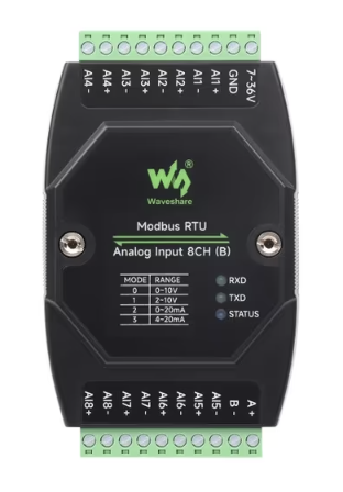
The Waveshare Industrial 8-CH (B) Analog Acquisition Module is a robust and versatile device designed for industrial applications. It is capable of measuring analog voltages in the range of 0 to 10 volts across 8 independent channels. This module is ideal for scenarios requiring simultaneous data acquisition from multiple analog sources, such as industrial automation, process monitoring, and control systems.

Explore Projects Built with Waveshare industrial 8-ch (b) analog acquisition module with default voltage mode (0—10v)

Use Cirkit Designer to design, explore, and prototype these projects online. Some projects support real-time simulation. Click "Open Project" to start designing instantly!
Cellular-Enabled IoT Device with Real-Time Clock and Power Management
Image of LRCM PHASE 2 BASIC: A project utilizing Waveshare industrial 8-ch (b) analog acquisition module with default voltage mode (0—10v) in a practical application
This circuit features a LilyGo-SIM7000G module for cellular communication and GPS functionality, interfaced with an RTC DS3231 for real-time clock capabilities. It includes voltage sensing through two voltage sensor modules, and uses an 8-channel opto-coupler for isolating different parts of the circuit. Power management is handled by a buck converter connected to a DC power source and batteries, with a fuse for protection and a rocker switch for on/off control. Additionally, there's an LED for indication purposes.
Cirkit Designer LogoOpen Project in Cirkit Designer
Arduino Mega 2560 Based Security System with Fingerprint Authentication and SMS Alerts
Image of Door security system: A project utilizing Waveshare industrial 8-ch (b) analog acquisition module with default voltage mode (0—10v) in a practical application
This circuit features an Arduino Mega 2560 microcontroller interfaced with a SIM800L GSM module, two fingerprint scanners, an I2C LCD display, an IR sensor, and a piezo buzzer. Power management is handled by a PowerBoost 1000 Basic Pad USB, a TP4056 charging module, and a Li-ion 18650 battery, with an option to use a Mini AC-DC 110V-230V to 5V 700mA module for direct power supply. The primary functionality appears to be a security system with GSM communication capabilities, biometric access control, and visual/audible feedback.
Cirkit Designer LogoOpen Project in Cirkit Designer
ESP32C3 and SIM800L Powered Smart Energy Monitor with OLED Display and Wi-Fi Connectivity
Image of SERVER: A project utilizing Waveshare industrial 8-ch (b) analog acquisition module with default voltage mode (0—10v) in a practical application
This circuit is a power monitoring system that uses an ESP32C3 microcontroller to collect power usage data from slave devices via WiFi and SMS. The collected data is displayed on a 0.96" OLED screen, and the system is powered by an AC-DC converter module. Additionally, the circuit includes a SIM800L GSM module for SMS communication and LEDs for status indication.
Cirkit Designer LogoOpen Project in Cirkit Designer
ESP32-Based Smart Energy Monitoring and Control System
Image of SMART SOCKET: A project utilizing Waveshare industrial 8-ch (b) analog acquisition module with default voltage mode (0—10v) in a practical application
This circuit is designed to monitor AC voltage and current using ZMPT101B and ZMCT103C sensors, respectively, with an ESP32 microcontroller processing the sensor outputs. The XL4015 step-down module regulates the power supply to provide a stable voltage to the sensors, the ESP32, and an LCD I2C display. The ESP32 controls a 4-channel relay module for switching AC loads, and the system's operation can be interacted with via the LCD display and a push switch.
Cirkit Designer LogoOpen Project in Cirkit Designer

Explore Projects Built with Waveshare industrial 8-ch (b) analog acquisition module with default voltage mode (0—10v)

Use Cirkit Designer to design, explore, and prototype these projects online. Some projects support real-time simulation. Click "Open Project" to start designing instantly!
Image of LRCM PHASE 2 BASIC: A project utilizing Waveshare industrial 8-ch (b) analog acquisition module with default voltage mode (0—10v) in a practical application
Cellular-Enabled IoT Device with Real-Time Clock and Power Management
This circuit features a LilyGo-SIM7000G module for cellular communication and GPS functionality, interfaced with an RTC DS3231 for real-time clock capabilities. It includes voltage sensing through two voltage sensor modules, and uses an 8-channel opto-coupler for isolating different parts of the circuit. Power management is handled by a buck converter connected to a DC power source and batteries, with a fuse for protection and a rocker switch for on/off control. Additionally, there's an LED for indication purposes.
Cirkit Designer LogoOpen Project in Cirkit Designer
Image of Door security system: A project utilizing Waveshare industrial 8-ch (b) analog acquisition module with default voltage mode (0—10v) in a practical application
Arduino Mega 2560 Based Security System with Fingerprint Authentication and SMS Alerts
This circuit features an Arduino Mega 2560 microcontroller interfaced with a SIM800L GSM module, two fingerprint scanners, an I2C LCD display, an IR sensor, and a piezo buzzer. Power management is handled by a PowerBoost 1000 Basic Pad USB, a TP4056 charging module, and a Li-ion 18650 battery, with an option to use a Mini AC-DC 110V-230V to 5V 700mA module for direct power supply. The primary functionality appears to be a security system with GSM communication capabilities, biometric access control, and visual/audible feedback.
Cirkit Designer LogoOpen Project in Cirkit Designer
Image of SERVER: A project utilizing Waveshare industrial 8-ch (b) analog acquisition module with default voltage mode (0—10v) in a practical application
ESP32C3 and SIM800L Powered Smart Energy Monitor with OLED Display and Wi-Fi Connectivity
This circuit is a power monitoring system that uses an ESP32C3 microcontroller to collect power usage data from slave devices via WiFi and SMS. The collected data is displayed on a 0.96" OLED screen, and the system is powered by an AC-DC converter module. Additionally, the circuit includes a SIM800L GSM module for SMS communication and LEDs for status indication.
Cirkit Designer LogoOpen Project in Cirkit Designer
Image of SMART SOCKET: A project utilizing Waveshare industrial 8-ch (b) analog acquisition module with default voltage mode (0—10v) in a practical application
ESP32-Based Smart Energy Monitoring and Control System
This circuit is designed to monitor AC voltage and current using ZMPT101B and ZMCT103C sensors, respectively, with an ESP32 microcontroller processing the sensor outputs. The XL4015 step-down module regulates the power supply to provide a stable voltage to the sensors, the ESP32, and an LCD I2C display. The ESP32 controls a 4-channel relay module for switching AC loads, and the system's operation can be interacted with via the LCD display and a push switch.
Cirkit Designer LogoOpen Project in Cirkit Designer

Common Applications

  • Industrial automation systems
  • Process monitoring and control
  • Data acquisition in laboratory environments
  • Sensor signal measurement and logging
  • IoT systems requiring multi-channel analog input

Technical Specifications

The following table outlines the key technical details of the Waveshare Industrial 8-CH (B) Analog Acquisition Module:

Parameter Specification
Input Voltage Range 0–10 V
Number of Channels 8
Communication Interface RS485 (Modbus RTU protocol)
Power Supply Voltage 9–24 V DC
Sampling Rate Up to 10 Hz per channel
Resolution 12-bit
Operating Temperature -40°C to 85°C
Dimensions 115 mm × 90 mm × 40 mm
Mounting DIN rail or wall-mounted

Pin Configuration and Descriptions

The module features a terminal block for power, communication, and analog input connections. Below is the pin configuration:

Pin Label Description
1 V+ Positive terminal for power supply (9–24 V DC)
2 GND Ground terminal for power supply
3 A+ RS485 communication line (positive)
4 B- RS485 communication line (negative)
5–12 CH1–CH8 Analog input channels (0–10 V)

Usage Instructions

How to Use the Module in a Circuit

  1. Power Connection: Connect a DC power supply (9–24 V) to the V+ and GND terminals.
  2. Analog Input: Connect the analog signal sources (e.g., sensors) to the CH1CH8 terminals. Ensure the input voltage does not exceed the 0–10 V range.
  3. Communication: Connect the A+ and B- terminals to an RS485-compatible device (e.g., PLC, computer with RS485 adapter, or microcontroller).
  4. Configuration: Use Modbus RTU commands to configure and read data from the module. Refer to the Modbus register map provided in the manufacturer's documentation.

Important Considerations and Best Practices

  • Ensure the input voltage for each channel remains within the 0–10 V range to avoid damage to the module.
  • Use shielded cables for RS485 communication to minimize noise and interference.
  • Terminate the RS485 bus with a 120-ohm resistor at both ends for reliable communication.
  • Mount the module securely on a DIN rail or wall to prevent vibration-related issues.
  • If using with a microcontroller like Arduino, ensure the RS485 adapter is properly connected and configured.

Example: Connecting to Arduino UNO

To interface the module with an Arduino UNO, you will need an RS485-to-TTL adapter. Below is an example Arduino sketch for reading data from the module:

#include <ModbusMaster.h>

// Instantiate ModbusMaster object
ModbusMaster node;

// RS485 communication pins
#define RE_PIN 2  // Receiver Enable pin
#define DE_PIN 3  // Driver Enable pin

void preTransmission() {
  digitalWrite(RE_PIN, HIGH); // Enable RS485 driver
  digitalWrite(DE_PIN, HIGH);
}

void postTransmission() {
  digitalWrite(RE_PIN, LOW);  // Disable RS485 driver
  digitalWrite(DE_PIN, LOW);
}

void setup() {
  // Initialize serial communication
  Serial.begin(9600); // For debugging
  Serial1.begin(9600); // RS485 communication

  // Configure RS485 control pins
  pinMode(RE_PIN, OUTPUT);
  pinMode(DE_PIN, OUTPUT);
  digitalWrite(RE_PIN, LOW);
  digitalWrite(DE_PIN, LOW);

  // Modbus communication setup
  node.begin(1, Serial1); // Set Modbus slave ID to 1
  node.preTransmission(preTransmission);
  node.postTransmission(postTransmission);
}

void loop() {
  uint8_t result;
  uint16_t data[8];

  // Read 8 registers starting from address 0x0000
  result = node.readInputRegisters(0x0000, 8);

  if (result == node.ku8MBSuccess) {
    for (int i = 0; i < 8; i++) {
      data[i] = node.getResponseBuffer(i);
      Serial.print("Channel ");
      Serial.print(i + 1);
      Serial.print(": ");
      Serial.println(data[i] * (10.0 / 4095.0)); // Convert to voltage
    }
  } else {
    Serial.print("Error: ");
    Serial.println(result);
  }

  delay(1000); // Wait 1 second before next read
}

Troubleshooting and FAQs

Common Issues and Solutions

  1. No Communication with the Module

    • Verify the RS485 connections (A+ and B-) and ensure they are not swapped.
    • Check the baud rate and Modbus slave ID in your software configuration.
    • Ensure the RS485 bus is properly terminated with 120-ohm resistors.
  2. Incorrect Voltage Readings

    • Confirm that the input voltage is within the 0–10 V range.
    • Check for loose or faulty connections on the analog input terminals.
    • Ensure the power supply voltage is stable and within the specified range.
  3. Module Not Powering On

    • Verify the power supply voltage is between 9–24 V DC.
    • Check the polarity of the power connections (V+ and GND).

FAQs

Q: Can this module measure negative voltages?
A: No, the module is designed to measure voltages in the range of 0–10 V only.

Q: What is the maximum cable length for RS485 communication?
A: RS485 supports cable lengths up to 1200 meters, but this may vary depending on baud rate and environmental noise.

Q: Can I use this module with a Raspberry Pi?
A: Yes, you can use an RS485-to-USB or RS485-to-TTL adapter to connect the module to a Raspberry Pi.

Q: Is the module compatible with 4–20 mA sensors?
A: Yes, but you will need a 250-ohm resistor to convert the 4–20 mA current signal to a 1–5 V voltage signal.