How to Use Raspberry Pi Compute Module 4 IO Board: Examples, Pinouts, and Specs
Introduction
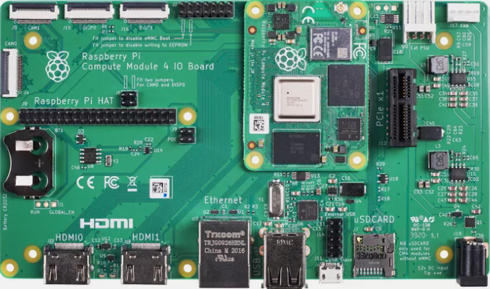
The Raspberry Pi Compute Module 4 IO Board (Manufacturer Part ID: CM4 IO Board) is a versatile interface board designed by the Raspberry Pi Foundation. It serves as a development platform for the Raspberry Pi Compute Module 4 (CM4), providing access to a wide range of input/output (I/O) ports. These include HDMI, USB, GPIO, PCIe, and more, making it an ideal choice for prototyping, development, and integration into custom applications.
Explore Projects Built with Raspberry Pi Compute Module 4 IO Board

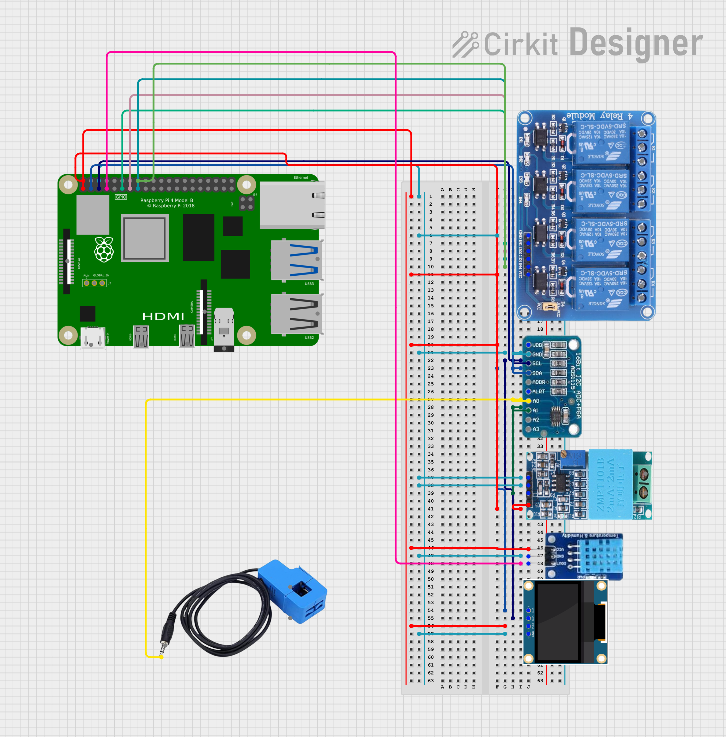

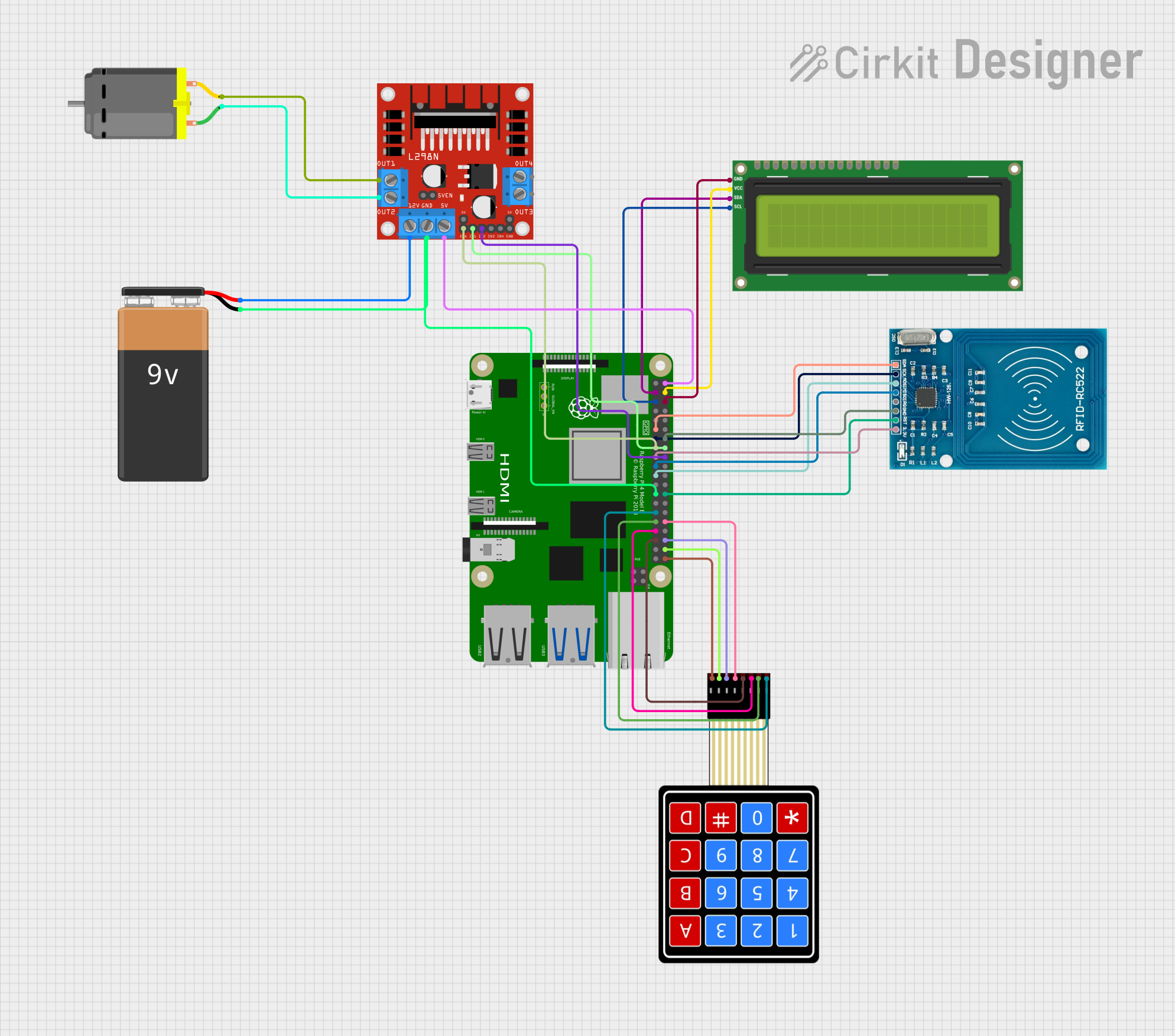
Explore Projects Built with Raspberry Pi Compute Module 4 IO Board
Common Applications and Use Cases
- Prototyping and testing with the Raspberry Pi Compute Module 4.
- Industrial and embedded systems development.
- Custom hardware integration for IoT, robotics, and automation.
- Media streaming and display applications using HDMI.
- USB-based peripherals and PCIe device integration.
Technical Specifications
The following are the key technical details of the Raspberry Pi Compute Module 4 IO Board:
General Specifications
- Power Input: 12V DC via barrel jack or GPIO header.
- Supported Compute Module: Raspberry Pi Compute Module 4 (CM4).
- Dimensions: 160mm x 90mm.
- Operating Temperature: -20°C to 85°C (dependent on CM4 module).
Key Features
- HDMI Ports: 2x full-size HDMI 2.0 ports.
- USB Ports: 2x USB 2.0 Type-A ports.
- Ethernet: Gigabit Ethernet port.
- PCIe Slot: 1x PCIe Gen 2 x1 slot.
- GPIO Header: 40-pin GPIO header (compatible with Raspberry Pi HATs).
- Camera and Display Interfaces: 2x MIPI CSI-2 camera connectors, 2x MIPI DSI display connectors.
- MicroSD Card Slot: For CM4 Lite variants (without onboard eMMC).
- Debug Interfaces: UART and JTAG headers for debugging.
Pin Configuration and Descriptions
GPIO Header (40-Pin)
The GPIO header provides access to various I/O pins. Below is the pinout:
| Pin Number | Pin Name | Description |
|---|---|---|
| 1 | 3.3V | 3.3V Power Output |
| 2 | 5V | 5V Power Output |
| 3 | GPIO2 (SDA1) | I2C1 Data Line |
| 4 | 5V | 5V Power Output |
| 5 | GPIO3 (SCL1) | I2C1 Clock Line |
| 6 | GND | Ground |
| 7 | GPIO4 | General Purpose I/O |
| 8 | GPIO14 (TXD0) | UART Transmit |
| 9 | GND | Ground |
| 10 | GPIO15 (RXD0) | UART Receive |
| ... | ... | ... |
For the full GPIO pinout, refer to the official Raspberry Pi documentation.
PCIe Slot
| Pin Group | Description |
|---|---|
| Power Pins | Supplies power to PCIe devices. |
| Data Pins | PCIe Gen 2 x1 data lanes. |
| Clock Pins | Provides clock signal for PCIe. |
Usage Instructions
How to Use the CM4 IO Board in a Circuit
- Install the Compute Module 4: Insert the CM4 into the IO Board's connector, ensuring proper alignment.
- Power the Board: Connect a 12V DC power supply to the barrel jack or use the GPIO header for power input.
- Connect Peripherals:
- Use the HDMI ports for display output.
- Connect USB devices (e.g., keyboard, mouse) to the USB Type-A ports.
- Attach cameras or displays to the MIPI CSI-2 and DSI connectors.
- Use the PCIe slot for compatible expansion cards.
- Access GPIO: Connect external devices to the 40-pin GPIO header for custom applications.
- Networking: Use the Gigabit Ethernet port for high-speed network connectivity.
Important Considerations and Best Practices
- Power Supply: Ensure the power supply provides sufficient current for the CM4 and connected peripherals.
- Cooling: Use a heatsink or fan for the CM4 if operating under heavy loads or in high-temperature environments.
- Static Protection: Handle the board with care to avoid electrostatic discharge (ESD) damage.
- Software Configuration: Use the Raspberry Pi Imager to flash the appropriate operating system onto the CM4's eMMC or microSD card.
Example: Using GPIO with Arduino UNO
The GPIO pins on the CM4 IO Board can interface with an Arduino UNO. Below is an example of controlling an LED connected to the GPIO pin using Python:
Import the GPIO library
import RPi.GPIO as GPIO import time
Set the GPIO mode to BCM (Broadcom pin numbering)
GPIO.setmode(GPIO.BCM)
Define the GPIO pin for the LED
LED_PIN = 18
Set up the LED pin as an output
GPIO.setup(LED_PIN, GPIO.OUT)
Blink the LED in a loop
try: while True: GPIO.output(LED_PIN, GPIO.HIGH) # Turn on the LED time.sleep(1) # Wait for 1 second GPIO.output(LED_PIN, GPIO.LOW) # Turn off the LED time.sleep(1) # Wait for 1 second except KeyboardInterrupt: # Clean up GPIO settings on exit GPIO.cleanup()
Notes:
- Connect the LED's anode to GPIO18 and cathode to GND via a 330-ohm resistor.
- Install the
RPi.GPIOlibrary usingpip install RPi.GPIOif not already installed.
Troubleshooting and FAQs
Common Issues
No Power to the Board:
- Ensure the power supply is connected and provides 12V DC.
- Check the power switch (if applicable) is turned on.
No Display Output:
- Verify the HDMI cable is securely connected.
- Ensure the correct HDMI port is selected on the display.
- Check the CM4's software configuration for display settings.
USB Devices Not Recognized:
- Confirm the USB devices are functional and compatible.
- Check for proper software drivers in the operating system.
GPIO Pins Not Working:
- Ensure the correct GPIO pin numbering is used in the code.
- Verify the GPIO pin is not being used by another function (e.g., I2C, SPI).
Solutions and Tips for Troubleshooting
- Debugging GPIO: Use a multimeter to check voltage levels on GPIO pins.
- Software Logs: Check system logs (
dmesgor/var/log/syslog) for error messages. - Firmware Updates: Ensure the CM4 firmware is up to date using the Raspberry Pi Imager.
For additional support, refer to the official Raspberry Pi documentation or community forums.