How to Use XL6009: Examples, Pinouts, and Specs
Introduction
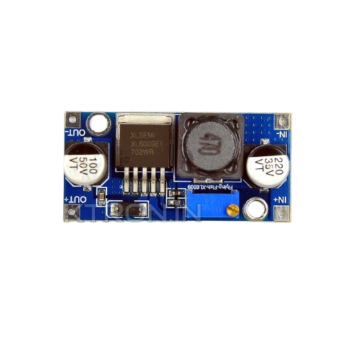
The XL6009 is a high-performance, step-up (boost) DC-DC converter designed to efficiently increase a lower input voltage to a higher output voltage. It is based on a high-frequency switching regulator, which ensures high efficiency and compact design. The XL6009 is widely used in applications requiring a stable output voltage from a varying input voltage, such as battery-powered devices, solar power systems, LED drivers, and portable electronics.
Explore Projects Built with XL6009


Explore Projects Built with XL6009
Common Applications:
- Battery-powered devices (e.g., powering 12V devices from a 5V USB source)
- Solar power systems
- LED drivers
- Portable electronics
- DIY electronics projects
- Powering sensors and modules in embedded systems
Technical Specifications
The XL6009 is a versatile component with the following key technical details:
Key Specifications:
- Input Voltage Range: 3V to 32V
- Output Voltage Range: 5V to 35V
- Switching Frequency: 400 kHz
- Efficiency: Up to 94%
- Output Current: Up to 4A (depending on input/output voltage and thermal conditions)
- Integrated Power MOSFET: 60V, 5A
- Operating Temperature: -40°C to +125°C
- Adjustable Output Voltage: Via onboard potentiometer (in most modules)
Pin Configuration and Descriptions:
The XL6009 is typically available as a module with the following pinout:
| Pin Name | Description |
|---|---|
| VIN | Input voltage pin. Connect the positive terminal of the input power source. |
| GND | Ground pin. Connect to the negative terminal of the input power source. |
| VOUT | Output voltage pin. Provides the boosted voltage to the load. |
| EN (optional) | Enable pin. Used to enable or disable the module (active high). |
Note: Some XL6009 modules may not expose the
ENpin. Check your specific module's datasheet or documentation.
Usage Instructions
How to Use the XL6009 in a Circuit:
Connect the Input Voltage:
- Connect the positive terminal of your power source to the
VINpin. - Connect the negative terminal of your power source to the
GNDpin.
- Connect the positive terminal of your power source to the
Connect the Load:
- Connect the positive terminal of your load to the
VOUTpin. - Connect the negative terminal of your load to the
GNDpin.
- Connect the positive terminal of your load to the
Adjust the Output Voltage:
- Use the onboard potentiometer (if available) to adjust the output voltage.
- Turn the potentiometer clockwise to increase the output voltage and counterclockwise to decrease it.
- Use a multimeter to measure the output voltage while adjusting.
Power On:
- Apply power to the
VINpin. The module will boost the input voltage to the desired output voltage.
- Apply power to the
Important Considerations and Best Practices:
- Input Voltage Range: Ensure the input voltage is within the specified range (3V to 32V).
- Output Voltage Range: Do not exceed the maximum output voltage of 35V.
- Current Limitations: The module can provide up to 4A, but this depends on the input/output voltage and thermal conditions. Use a heatsink if necessary.
- Load Connection: Always connect the load after setting the desired output voltage to avoid damaging sensitive components.
- Filtering Capacitors: Use appropriate input and output capacitors to reduce voltage ripple and improve stability.
Example: Using XL6009 with Arduino UNO
The XL6009 can be used to power an Arduino UNO from a lower voltage source (e.g., a 3.7V Li-ion battery). Here's an example:
- Connect the battery's positive terminal to the
VINpin and the negative terminal toGND. - Adjust the output voltage to 9V using the potentiometer.
- Connect the
VOUTpin to the Arduino'sVINpin andGNDtoGND.
Here is a simple Arduino code to blink an LED while powered by the XL6009:
// Simple LED Blink Example
// This code blinks an LED connected to pin 13 of the Arduino UNO.
// Ensure the XL6009 is providing a stable 9V to the Arduino's VIN pin.

void setup() {
  pinMode(13, OUTPUT); // Set pin 13 as an output
}

void loop() {
  digitalWrite(13, HIGH); // Turn the LED on
  delay(1000);            // Wait for 1 second
  digitalWrite(13, LOW);  // Turn the LED off
  delay(1000);            // Wait for 1 second
}
Troubleshooting and FAQs
Common Issues and Solutions:
No Output Voltage:
- Cause: Input voltage is too low or not connected properly.
- Solution: Verify the input voltage is within the 3V to 32V range and connections are secure.
Output Voltage is Unstable:
- Cause: Insufficient input/output capacitors or high load current.
- Solution: Add appropriate capacitors (e.g., 100µF electrolytic) to the input and output.
Output Voltage Does Not Match the Set Value:
- Cause: Potentiometer not adjusted correctly or load is too high.
- Solution: Re-adjust the potentiometer and ensure the load current is within the module's limits.
Module Overheats:
- Cause: Excessive current draw or poor ventilation.
- Solution: Reduce the load current or add a heatsink to the module.
FAQs:
Q: Can the XL6009 step down voltage?
A: No, the XL6009 is a step-up (boost) converter and cannot step down voltage.Q: Can I use the XL6009 to power a Raspberry Pi?
A: Yes, but ensure the output voltage is set to 5V and the module can handle the current demand (typically 2.5A for a Raspberry Pi 4).Q: How do I calculate the efficiency of the XL6009?
A: Efficiency (%) = (Output Power / Input Power) × 100. Measure the input and output voltage/current to calculate.Q: Is the XL6009 suitable for audio applications?
A: It can be used, but additional filtering may be required to reduce noise.
By following this documentation, you can effectively use the XL6009 in your projects and troubleshoot common issues.