How to Use rele RAS 0510: Examples, Pinouts, and Specs
Introduction
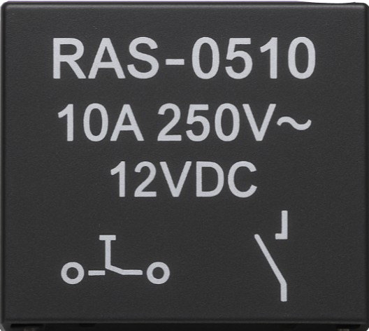
The RAS 0510 is a relay designed for switching applications, featuring a compact design and reliable performance. It is commonly used in automation and control systems to manage high voltage or current loads with low voltage control signals. This relay acts as an electrically operated switch, allowing a small input signal to control larger electrical loads safely and efficiently.
Explore Projects Built with rele RAS 0510
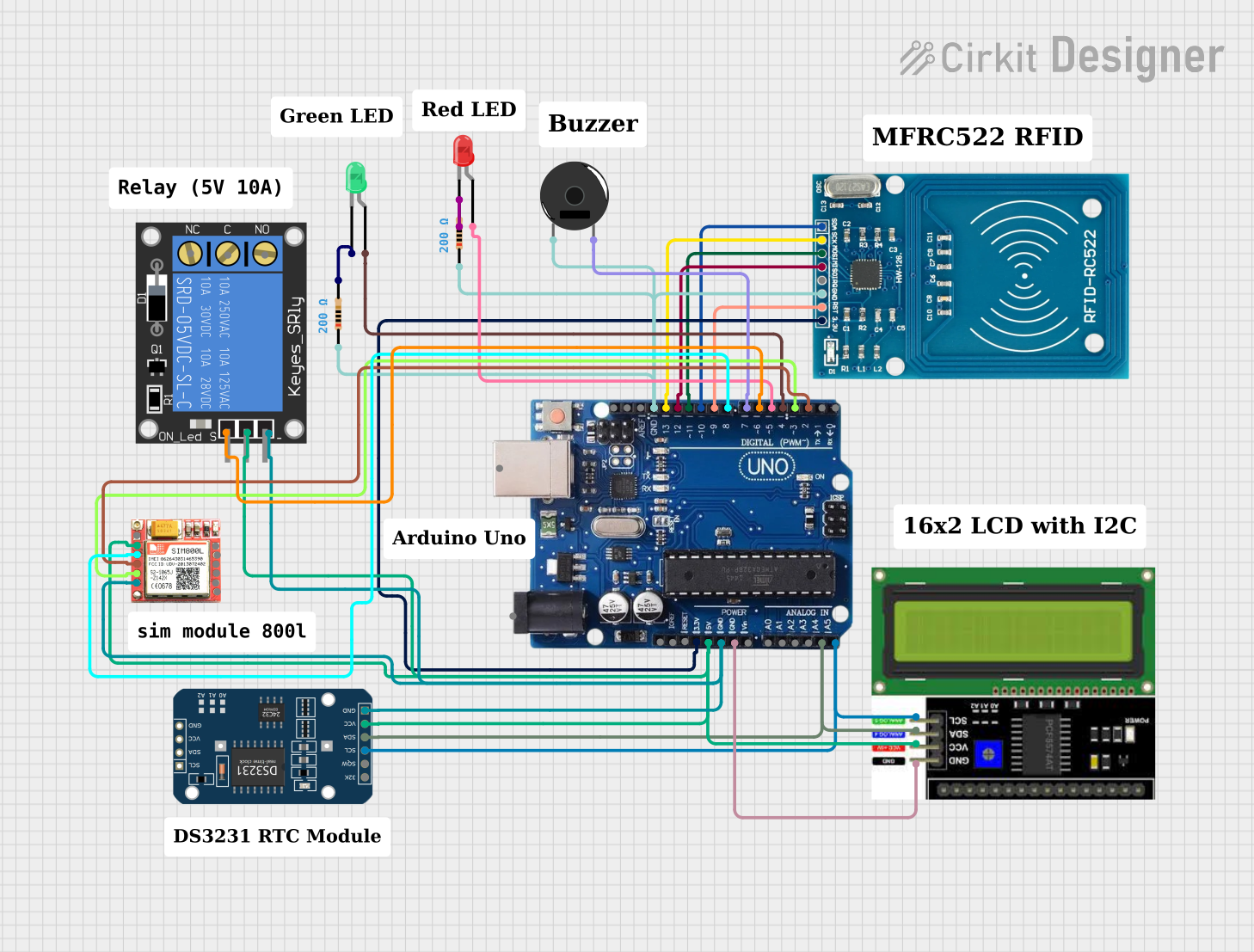
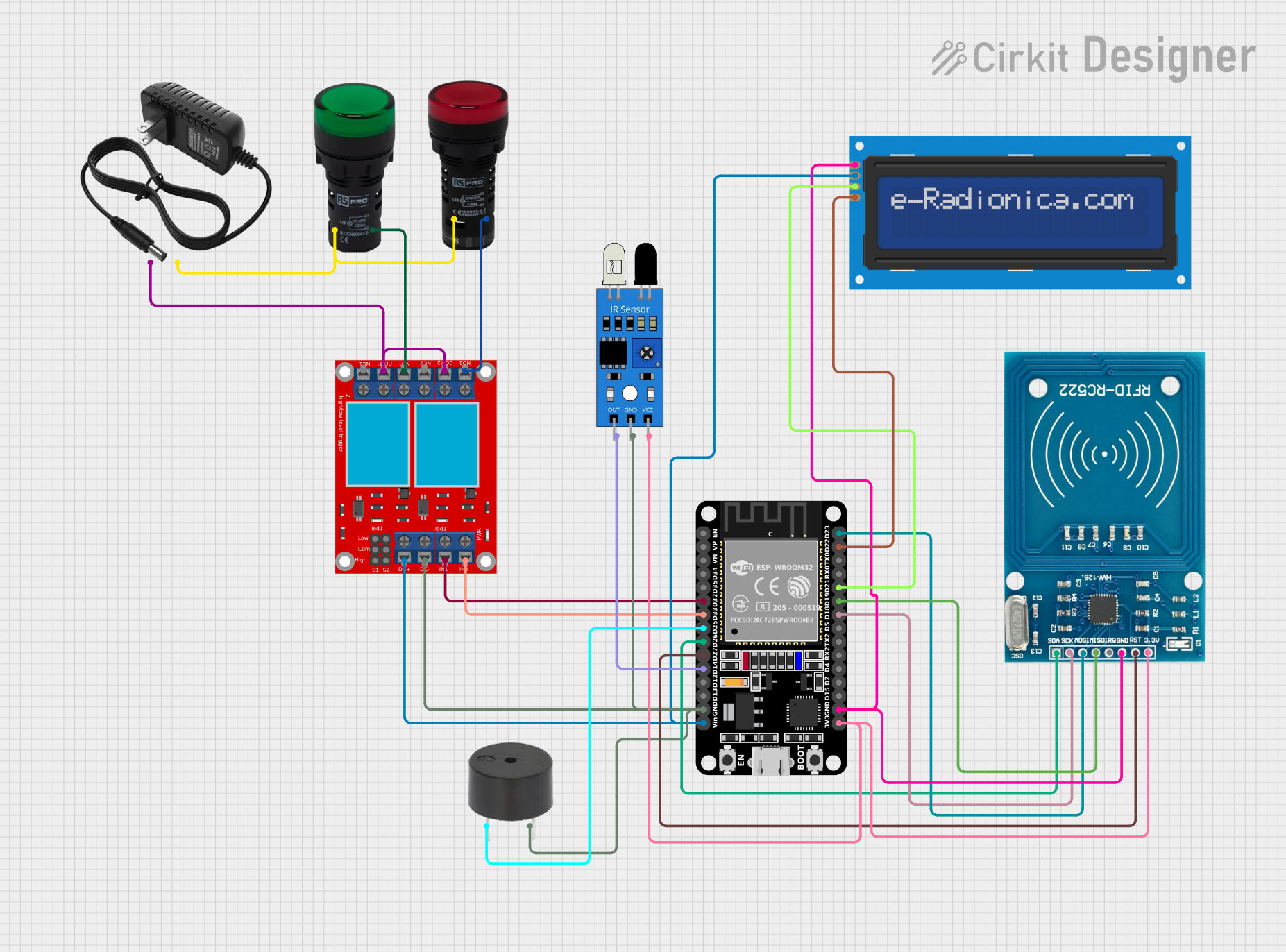
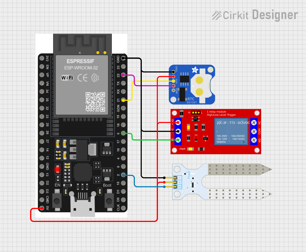
Explore Projects Built with rele RAS 0510
Common Applications and Use Cases
- Home automation systems
- Industrial control panels
- Motor control circuits
- Lighting systems
- HVAC (Heating, Ventilation, and Air Conditioning) systems
- Safety and alarm systems
Technical Specifications
The RAS 0510 relay is designed to handle a wide range of applications with the following specifications:
| Parameter | Value |
|---|---|
| Coil Voltage | 5V DC |
| Coil Resistance | 100 Ω |
| Contact Configuration | SPDT (Single Pole Double Throw) |
| Contact Rating | 10A @ 250V AC / 10A @ 30V DC |
| Switching Voltage (Max) | 250V AC / 30V DC |
| Switching Current (Max) | 10A |
| Operate Time | ≤ 10 ms |
| Release Time | ≤ 5 ms |
| Insulation Resistance | ≥ 100 MΩ @ 500V DC |
| Dielectric Strength | 1500V AC (1 min) |
| Operating Temperature | -40°C to +85°C |
| Dimensions | 19.0 x 15.5 x 15.0 mm |
| Weight | ~10g |
Pin Configuration and Descriptions
The RAS 0510 relay has a standard 5-pin configuration. The table below describes each pin:
| Pin Number | Name | Description |
|---|---|---|
| 1 | Coil (+) | Positive terminal of the relay coil. Connect to the control voltage (e.g., 5V). |
| 2 | Coil (-) | Negative terminal of the relay coil. Connect to ground. |
| 3 | Common (COM) | Common terminal for the relay's switching contacts. |
| 4 | Normally Open (NO) | Contact that remains open until the relay is activated. |
| 5 | Normally Closed (NC) | Contact that remains closed until the relay is activated. |
Usage Instructions
How to Use the RAS 0510 in a Circuit
- Power the Coil: Connect the coil terminals (Pin 1 and Pin 2) to a 5V DC power source. Ensure the current-limiting resistor is appropriate for the coil resistance (100 Ω).
- Connect the Load:
- Connect the load to the Common (COM) terminal (Pin 3).
- Use the Normally Open (NO) terminal (Pin 4) if you want the load to be powered only when the relay is activated.
- Use the Normally Closed (NC) terminal (Pin 5) if you want the load to be powered when the relay is not activated.
- Control the Relay: Use a microcontroller, such as an Arduino UNO, or a transistor circuit to control the relay coil.
Important Considerations and Best Practices
- Flyback Diode: Always connect a flyback diode across the relay coil to protect the control circuit from voltage spikes when the relay is deactivated.
- Isolation: Use an optocoupler or transistor driver circuit to isolate the control circuit from the high voltage load.
- Power Ratings: Ensure the load does not exceed the relay's maximum current and voltage ratings.
- Ventilation: Provide adequate ventilation to prevent overheating during prolonged use.
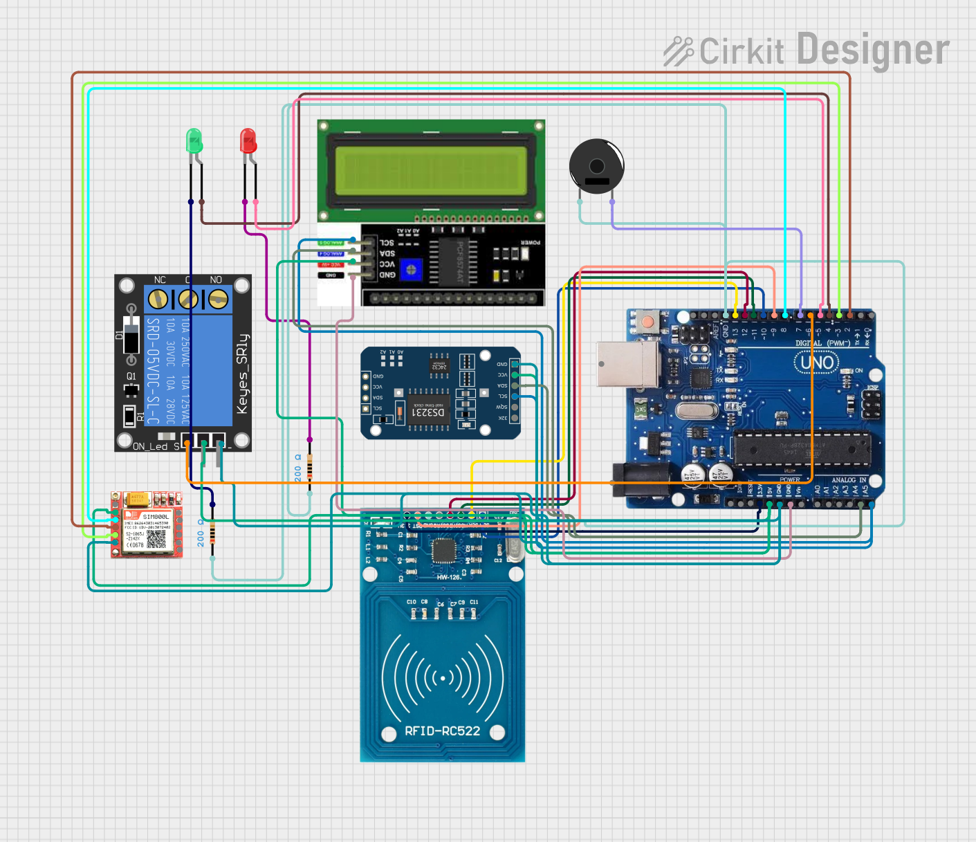
Example: Connecting the RAS 0510 to an Arduino UNO
Below is an example of how to control the RAS 0510 relay using an Arduino UNO:
Circuit Diagram
- Connect Pin 1 (Coil +) to a digital output pin on the Arduino (e.g., Pin 7) through a transistor.
- Connect Pin 2 (Coil -) to the Arduino's GND.
- Connect the load to the COM and NO terminals of the relay.
Arduino Code
// Define the pin connected to the relay
const int relayPin = 7;

void setup() {
  pinMode(relayPin, OUTPUT); // Set the relay pin as an output
  digitalWrite(relayPin, LOW); // Ensure the relay is off at startup
}

void loop() {
  digitalWrite(relayPin, HIGH); // Activate the relay
  delay(1000); // Keep the relay on for 1 second
  digitalWrite(relayPin, LOW); // Deactivate the relay
  delay(1000); // Keep the relay off for 1 second
}
Troubleshooting and FAQs
Common Issues and Solutions
Relay Not Activating:
- Cause: Insufficient voltage or current to the coil.
- Solution: Verify the control voltage is 5V DC and the current is sufficient to energize the coil.
Load Not Switching:
- Cause: Incorrect wiring of the load to the relay terminals.
- Solution: Double-check the connections to the COM, NO, and NC terminals.
Voltage Spikes Damaging the Circuit:
- Cause: Absence of a flyback diode across the relay coil.
- Solution: Install a flyback diode (e.g., 1N4007) across the coil terminals.
Relay Overheating:
- Cause: Exceeding the relay's current or voltage ratings.
- Solution: Ensure the load does not exceed 10A or 250V AC / 30V DC.
FAQs
Q1: Can I use the RAS 0510 relay with a 3.3V control signal?
A1: No, the RAS 0510 requires a 5V DC control signal to operate reliably. Use a level shifter or transistor circuit if your control signal is 3.3V.
Q2: Is the RAS 0510 suitable for switching DC motors?
A2: Yes, as long as the motor's current and voltage do not exceed the relay's maximum ratings (10A @ 30V DC).
Q3: Can I use the RAS 0510 for high-frequency switching?
A3: No, mechanical relays like the RAS 0510 are not suitable for high-frequency switching due to their slower response times and mechanical wear.
Q4: What is the lifespan of the RAS 0510 relay?
A4: The relay's lifespan depends on the load and switching frequency. Under normal conditions, it can last for tens of thousands of cycles.