Cirkit Designer Logo
Cirkit Designer
Your all-in-one circuit design IDE
Home / 
Component Documentation

How to Use NMOSFET AO3400A: Examples, Pinouts, and Specs

Image of NMOSFET AO3400A
Cirkit Designer LogoDesign with NMOSFET AO3400A in Cirkit Designer

Introduction

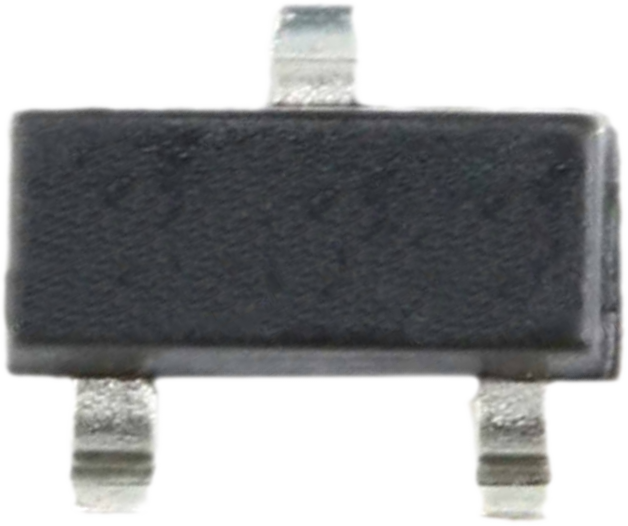
The AO3400A is an N-channel MOSFET manufactured by Generic. It is designed for low-voltage applications and features low on-resistance and fast switching speeds. This makes it an ideal choice for power management, load switching, DC-DC converters, and other switching applications. Its compact SOT-23 package allows for easy integration into space-constrained designs.

Explore Projects Built with NMOSFET AO3400A

Use Cirkit Designer to design, explore, and prototype these projects online. Some projects support real-time simulation. Click "Open Project" to start designing instantly!
Pixhawk-Controlled Solenoid Driver with Voltage Regulation
Image of solenoid control circuit: A project utilizing NMOSFET AO3400A in a practical application
This circuit uses an LM393 comparator to drive an IRFZ44N MOSFET based on the comparison between two input signals from a pixhawk 2.4.8 flight controller. The MOSFET switches a solenoid, with a diode for back EMF protection, and the system is powered by a Lipo battery with voltage regulation provided by a step-up boost converter and a step-down voltage regulator to ensure stable operation. A resistor is connected to the gate of the MOSFET for proper biasing.
Cirkit Designer LogoOpen Project in Cirkit Designer
STM32 Nucleo-Controlled Solenoid Actuation System
Image of stm32 braile: A project utilizing NMOSFET AO3400A in a practical application
This circuit appears to be a microcontroller-driven array of push-pull solenoids with flyback diodes for protection. The STM32 Nucleo F303RE microcontroller's GPIO pins are connected to the gates of several nMOS transistors, which act as switches to control the current flow to the solenoids. A pushbutton with a pull-up resistor is also interfaced with the microcontroller for user input, and the power supply is connected to the solenoids with ground return paths through the nMOS transistors.
Cirkit Designer LogoOpen Project in Cirkit Designer
Arduino Nano Multiwatt Charger with OLED Display and Keypad Control
Image of MULTIWATT CHARGER: A project utilizing NMOSFET AO3400A in a practical application
This circuit is a multiwatt charger controlled by an Arduino Nano, featuring a 4x4 membrane keypad for user input, a 0.96" OLED display for output, and a DS3502 digital potentiometer for voltage adjustment. It measures voltage and current using analog inputs and adjusts the output voltage to achieve a user-defined power target, powered by a 12V battery and regulated by an XL6009 voltage regulator.
Cirkit Designer LogoOpen Project in Cirkit Designer
Battery-Powered LM393-Based Voltage Comparator Circuit with MOSFET Control
Image of cut off charger: A project utilizing NMOSFET AO3400A in a practical application
This circuit is a power regulation and control system that uses an LM393 comparator to monitor voltage levels and control a MOSFET (IRFZ44N) for switching. It is powered by a 12V battery and a USB power source, and includes various resistors and capacitors for filtering and stabilization.
Cirkit Designer LogoOpen Project in Cirkit Designer

Explore Projects Built with NMOSFET AO3400A

Use Cirkit Designer to design, explore, and prototype these projects online. Some projects support real-time simulation. Click "Open Project" to start designing instantly!
Image of solenoid control circuit: A project utilizing NMOSFET AO3400A in a practical application
Pixhawk-Controlled Solenoid Driver with Voltage Regulation
This circuit uses an LM393 comparator to drive an IRFZ44N MOSFET based on the comparison between two input signals from a pixhawk 2.4.8 flight controller. The MOSFET switches a solenoid, with a diode for back EMF protection, and the system is powered by a Lipo battery with voltage regulation provided by a step-up boost converter and a step-down voltage regulator to ensure stable operation. A resistor is connected to the gate of the MOSFET for proper biasing.
Cirkit Designer LogoOpen Project in Cirkit Designer
Image of stm32 braile: A project utilizing NMOSFET AO3400A in a practical application
STM32 Nucleo-Controlled Solenoid Actuation System
This circuit appears to be a microcontroller-driven array of push-pull solenoids with flyback diodes for protection. The STM32 Nucleo F303RE microcontroller's GPIO pins are connected to the gates of several nMOS transistors, which act as switches to control the current flow to the solenoids. A pushbutton with a pull-up resistor is also interfaced with the microcontroller for user input, and the power supply is connected to the solenoids with ground return paths through the nMOS transistors.
Cirkit Designer LogoOpen Project in Cirkit Designer
Image of MULTIWATT CHARGER: A project utilizing NMOSFET AO3400A in a practical application
Arduino Nano Multiwatt Charger with OLED Display and Keypad Control
This circuit is a multiwatt charger controlled by an Arduino Nano, featuring a 4x4 membrane keypad for user input, a 0.96" OLED display for output, and a DS3502 digital potentiometer for voltage adjustment. It measures voltage and current using analog inputs and adjusts the output voltage to achieve a user-defined power target, powered by a 12V battery and regulated by an XL6009 voltage regulator.
Cirkit Designer LogoOpen Project in Cirkit Designer
Image of cut off charger: A project utilizing NMOSFET AO3400A in a practical application
Battery-Powered LM393-Based Voltage Comparator Circuit with MOSFET Control
This circuit is a power regulation and control system that uses an LM393 comparator to monitor voltage levels and control a MOSFET (IRFZ44N) for switching. It is powered by a 12V battery and a USB power source, and includes various resistors and capacitors for filtering and stabilization.
Cirkit Designer LogoOpen Project in Cirkit Designer

Common Applications

  • Power management in portable devices
  • Load switching in low-voltage circuits
  • DC-DC converters
  • Motor drivers
  • LED drivers

Technical Specifications

Key Specifications

Parameter Value
Manufacturer Part ID AO3400A
Type N-Channel MOSFET
Maximum Drain-Source Voltage (VDS) 30V
Maximum Gate-Source Voltage (VGS) ±20V
Continuous Drain Current (ID) 5.8A (at 10V VGS)
Pulsed Drain Current (IDM) 20A
Maximum Power Dissipation (PD) 1.4W
RDS(on) (On-Resistance) 13.5mΩ (at 10V VGS)
Gate Threshold Voltage (VGS(th)) 1.0V to 2.5V
Operating Temperature Range -55°C to 150°C
Package Type SOT-23

Pin Configuration

The AO3400A is housed in a 3-pin SOT-23 package. The pinout is as follows:

Pin Number Pin Name Description
1 Gate Controls the MOSFET switching
2 Source Connected to ground or low side
3 Drain Connected to the load

Usage Instructions

How to Use the AO3400A in a Circuit

  1. Power Supply Requirements: Ensure the drain-source voltage (VDS) does not exceed 30V and the gate-source voltage (VGS) stays within ±20V.
  2. Gate Drive Voltage: For optimal performance, drive the gate with a voltage of 10V. However, the AO3400A can operate with a gate voltage as low as 4.5V for low-power applications.
  3. Load Connection: Connect the load between the drain pin and the positive supply voltage. The source pin should be connected to ground.
  4. Gate Resistor: Use a resistor (typically 10Ω to 100Ω) in series with the gate to limit inrush current and prevent oscillations.
  5. Flyback Diode: If driving an inductive load (e.g., motor or relay), add a flyback diode across the load to protect the MOSFET from voltage spikes.

Example Circuit with Arduino UNO

The AO3400A can be used to control a load (e.g., an LED or motor) with an Arduino UNO. Below is an example circuit and code:

Circuit Description

  • Connect the source pin of the AO3400A to ground.
  • Connect the drain pin to one terminal of the load (e.g., an LED with a current-limiting resistor).
  • Connect the other terminal of the load to the positive supply voltage.
  • Connect the gate pin to a digital output pin of the Arduino through a 100Ω resistor.

Arduino Code

// Example code to control an AO3400A MOSFET with an Arduino UNO
// This code turns the MOSFET on and off to control a load (e.g., an LED).

const int mosfetGatePin = 9; // Pin connected to the gate of the AO3400A

void setup() {
  pinMode(mosfetGatePin, OUTPUT); // Set the gate pin as an output
}

void loop() {
  digitalWrite(mosfetGatePin, HIGH); // Turn the MOSFET on (load is powered)
  delay(1000); // Wait for 1 second
  digitalWrite(mosfetGatePin, LOW);  // Turn the MOSFET off (load is off)
  delay(1000); // Wait for 1 second
}

Important Considerations

  • Thermal Management: Ensure adequate heat dissipation, especially when operating at high currents. Use a heatsink or proper PCB design to manage heat.
  • Voltage Spikes: Protect the MOSFET from voltage spikes using appropriate snubber circuits or diodes.
  • Gate Drive Voltage: Avoid exceeding the maximum gate-source voltage (±20V) to prevent damage.

Troubleshooting and FAQs

Common Issues and Solutions

  1. MOSFET Overheating

    • Cause: High current or insufficient heat dissipation.
    • Solution: Check the load current and ensure it is within the MOSFET's rated limits. Improve heat dissipation using a heatsink or better PCB design.
  2. MOSFET Not Switching Properly

    • Cause: Insufficient gate drive voltage.
    • Solution: Ensure the gate voltage is at least 4.5V for low-power applications or 10V for optimal performance.
  3. Load Not Turning Off Completely

    • Cause: Gate voltage not fully dropping to 0V.
    • Solution: Check for leakage currents or improper grounding. Add a pull-down resistor (10kΩ) between the gate and source.
  4. MOSFET Damaged

    • Cause: Exceeding voltage or current ratings.
    • Solution: Verify that the circuit operates within the specified voltage and current limits. Add protection components like diodes or TVS (Transient Voltage Suppressors) if necessary.

FAQs

Q1: Can the AO3400A be used with 3.3V logic?
A1: While the AO3400A can operate with a gate voltage as low as 4.5V, it is not guaranteed to fully turn on with 3.3V logic. Consider using a logic-level MOSFET for 3.3V systems.

Q2: Is the AO3400A suitable for high-frequency switching?
A2: Yes, the AO3400A has fast switching characteristics, making it suitable for high-frequency applications. However, ensure proper gate drive circuitry to minimize switching losses.

Q3: Can I use the AO3400A for AC loads?
A3: No, the AO3400A is designed for DC applications. For AC loads, consider using a TRIAC or other AC-specific components.

Q4: What is the maximum load current the AO3400A can handle?
A4: The AO3400A can handle up to 5.8A continuously at 10V gate drive, provided proper thermal management is in place.