
How to Use Kingbright TA07-11 5x7 LED Matrix (Column Anode): Examples, Pinouts, and Specs
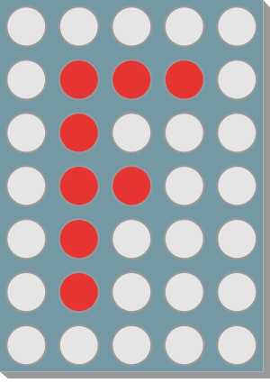
 Design with Kingbright TA07-11 5x7 LED Matrix (Column Anode) in Cirkit Designer
Introduction
The Kingbright TA07-11 is a 5x7 LED matrix display designed for visual output in a variety of applications. It features a column anode configuration, which simplifies the control of individual LEDs in the grid. This component is ideal for creating alphanumeric displays, simple graphics, and visual indicators in embedded systems, consumer electronics, and industrial equipment.
Explore Projects Built with Kingbright TA07-11 5x7 LED Matrix (Column Anode)
 Open Project in Cirkit Designer
 Open Project in Cirkit Designer
 Open Project in Cirkit Designer
 Open Project in Cirkit Designer
Explore Projects Built with Kingbright TA07-11 5x7 LED Matrix (Column Anode)
Open Project in Cirkit DesignerOpen Project in Cirkit DesignerOpen Project in Cirkit DesignerOpen Project in Cirkit DesignerCommon Applications
- Alphanumeric character displays
- Scrolling text or animations
- Visual indicators in control panels
- Educational projects and prototyping
- Embedded systems requiring compact visual output
Technical Specifications
Key Technical Details
| Parameter | Value |
|---|---|
| Manufacturer | Kingbright |
| Model Number | TA07-11 |
| LED Configuration | 5x7 matrix (35 LEDs) |
| LED Color | Red |
| Forward Voltage (per LED) | 2.0V (typical) |
| Forward Current (per LED) | 20mA (maximum) |
| Reverse Voltage | 5V (maximum) |
| Power Dissipation | 70mW (maximum per LED) |
| Operating Temperature | -40°C to +85°C |
| Dimensions | 19.9mm x 15.0mm x 6.5mm |
Pin Configuration and Descriptions
The TA07-11 has 14 pins, with rows connected to cathodes and columns connected to anodes. Below is the pinout:
| Pin Number | Description | Connection Type |
|---|---|---|
| 1 | Row 1 Cathode | Cathode |
| 2 | Row 2 Cathode | Cathode |
| 3 | Row 3 Cathode | Cathode |
| 4 | Row 4 Cathode | Cathode |
| 5 | Row 5 Cathode | Cathode |
| 6 | Column 5 Anode | Anode |
| 7 | Column 4 Anode | Anode |
| 8 | Column 3 Anode | Anode |
| 9 | Column 2 Anode | Anode |
| 10 | Column 1 Anode | Anode |
| 11 | Row 7 Cathode | Cathode |
| 12 | Row 6 Cathode | Cathode |
| 13 | Not Connected (NC) | - |
| 14 | Not Connected (NC) | - |
Usage Instructions
How to Use the Component in a Circuit
- Power Requirements: Ensure that the forward voltage (2.0V per LED) and forward current (20mA per LED) are not exceeded. Use current-limiting resistors to protect the LEDs.
- Matrix Control: Use a microcontroller or driver IC to control the rows and columns. Activate one row at a time while driving the corresponding column anodes to light up specific LEDs.
- Multiplexing: Implement multiplexing to control all 35 LEDs with fewer GPIO pins. This involves rapidly switching between rows while updating the column states.
Example Circuit with Arduino UNO
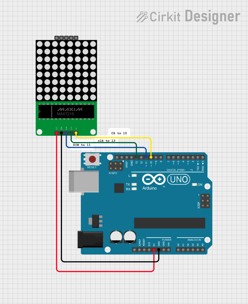
Below is an example of how to connect the TA07-11 to an Arduino UNO for basic operation:
Circuit Connections
- Connect the row cathodes (pins 1-5, 11-12) to digital pins on the Arduino through current-limiting resistors.
- Connect the column anodes (pins 6-10) to additional digital pins on the Arduino.
- Use a common ground between the Arduino and the LED matrix.
Example Code
// Example code to light up a single LED in the Kingbright TA07-11 5x7 LED matrix
// This example assumes the matrix is connected to Arduino digital pins 2-12

// Define row and column pins
const int rowPins[7] = {2, 3, 4, 5, 6, 7, 8}; // Rows 1-7 cathodes
const int colPins[5] = {9, 10, 11, 12, 13};   // Columns 1-5 anodes

void setup() {
  // Set all row and column pins as outputs
  for (int i = 0; i < 7; i++) {
    pinMode(rowPins[i], OUTPUT);
    digitalWrite(rowPins[i], HIGH); // Turn off rows (active LOW)
  }
  for (int i = 0; i < 5; i++) {
    pinMode(colPins[i], OUTPUT);
    digitalWrite(colPins[i], LOW); // Turn off columns (active HIGH)
  }
}

void loop() {
  // Light up the LED at Row 3, Column 2
  digitalWrite(rowPins[2], LOW);  // Activate Row 3 (active LOW)
  digitalWrite(colPins[1], HIGH); // Activate Column 2 (active HIGH)
  delay(500);                     // Keep the LED on for 500ms

  // Turn off the LED
  digitalWrite(rowPins[2], HIGH); // Deactivate Row 3
  digitalWrite(colPins[1], LOW);  // Deactivate Column 2
  delay(500);                     // Wait for 500ms
}
Important Considerations and Best Practices
- Current Limiting: Always use resistors to limit the current through each LED. Calculate the resistor value using Ohm's Law: ( R = \frac{V_{supply} - V_{forward}}{I_{forward}} ).
- Multiplexing Frequency: Use a refresh rate of at least 60Hz to avoid visible flickering.
- Heat Management: Avoid driving all LEDs at maximum current simultaneously to prevent overheating.
Troubleshooting and FAQs
Common Issues
LEDs Not Lighting Up:
- Check the wiring and ensure all connections are secure.
- Verify that the current-limiting resistors are correctly calculated and installed.
- Ensure the microcontroller pins are configured as outputs.
Flickering LEDs:
- Increase the multiplexing frequency to reduce visible flicker.
- Ensure the power supply can handle the current demand of the matrix.
Dim LEDs:
- Verify that the forward current is sufficient (20mA per LED).
- Check for voltage drops across the resistors or wiring.
Solutions and Tips
- Use a dedicated LED driver IC (e.g., MAX7219) for easier control and reduced microcontroller pin usage.
- Test the matrix with a multimeter to identify faulty LEDs or connections.
- For complex animations or patterns, consider using libraries like the Arduino LEDControl library.
By following this documentation, you can effectively integrate the Kingbright TA07-11 5x7 LED matrix into your projects for reliable and visually appealing results.