How to Use 4 Channel Relay Module: Examples, Pinouts, and Specs
Introduction
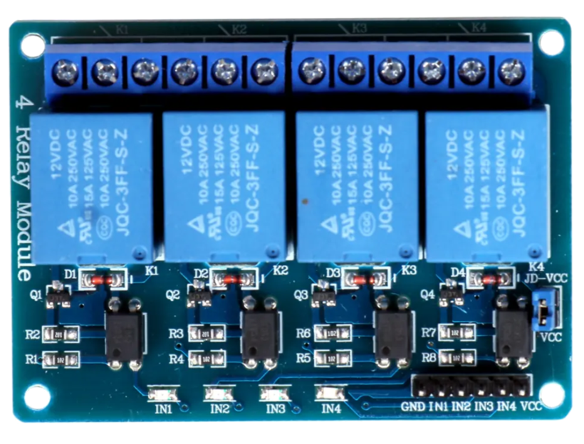
The 4 Channel Relay Module is an electronic component designed to control up to four independent circuits using a single microcontroller or switch. Each relay on the module acts as an electrically operated switch, allowing low-power control signals to manage high-power devices. This makes the module ideal for applications such as home automation, industrial control systems, and robotics.
Explore Projects Built with 4 Channel Relay Module


Explore Projects Built with 4 Channel Relay Module
Common Applications and Use Cases
- Home automation (e.g., controlling lights, fans, or appliances)
- Industrial equipment control
- Robotics and motor control
- IoT (Internet of Things) projects
- Smart home systems
Technical Specifications
The 4 Channel Relay Module is designed to interface with microcontrollers like Arduino, Raspberry Pi, and other control systems. Below are its key technical details:
General Specifications
- Operating Voltage: 5V DC
- Trigger Voltage: 3.3V to 5V (compatible with most microcontrollers)
- Relay Type: SPDT (Single Pole Double Throw)
- Maximum Load (per relay):
- AC: 250V at 10A
- DC: 30V at 10A
- Isolation: Optocoupler isolation for safe operation
- Dimensions: ~75mm x 55mm x 20mm
- Weight: ~70g
Pin Configuration and Descriptions
The module has two main interfaces: the control pins and the relay output terminals.
Control Pins
| Pin Name | Description |
|---|---|
| VCC | Power supply input (5V DC) |
| GND | Ground connection |
| IN1 | Control signal for Relay 1 (Active Low) |
| IN2 | Control signal for Relay 2 (Active Low) |
| IN3 | Control signal for Relay 3 (Active Low) |
| IN4 | Control signal for Relay 4 (Active Low) |
Relay Output Terminals
Each relay has three output terminals:
| Terminal | Description |
|---|---|
| NO (Normally Open) | Open circuit when the relay is inactive. Closes when activated. |
| NC (Normally Closed) | Closed circuit when the relay is inactive. Opens when activated. |
| COM (Common) | Common terminal for the relay. Connects to NO or NC. |
Usage Instructions
How to Use the 4 Channel Relay Module in a Circuit
Power the Module:
- Connect the VCC pin to a 5V DC power source.
- Connect the GND pin to the ground of your power source or microcontroller.
Connect the Control Signals:
- Connect the IN1, IN2, IN3, and IN4 pins to the digital output pins of your microcontroller.
- Ensure the microcontroller's ground is connected to the module's GND.
Connect the Load:
- For each relay, connect the device you want to control to the COM and NO or NC terminals, depending on your desired behavior:
- Use NO for devices that should be off by default.
- Use NC for devices that should be on by default.
- For each relay, connect the device you want to control to the COM and NO or NC terminals, depending on your desired behavior:
Control the Relays:
- Send a LOW signal (0V) to the corresponding IN pin to activate the relay.
- Send a HIGH signal (5V) to deactivate the relay.
Important Considerations and Best Practices
- Power Supply: Ensure the module is powered with a stable 5V DC supply. Using a higher voltage may damage the module.
- Isolation: The module uses optocouplers for isolation, but always exercise caution when working with high voltages.
- Load Ratings: Do not exceed the maximum load ratings (250V AC/10A or 30V DC/10A) to avoid damage or hazards.
- Active Low Logic: The relays are triggered by a LOW signal. Ensure your microcontroller code accounts for this.
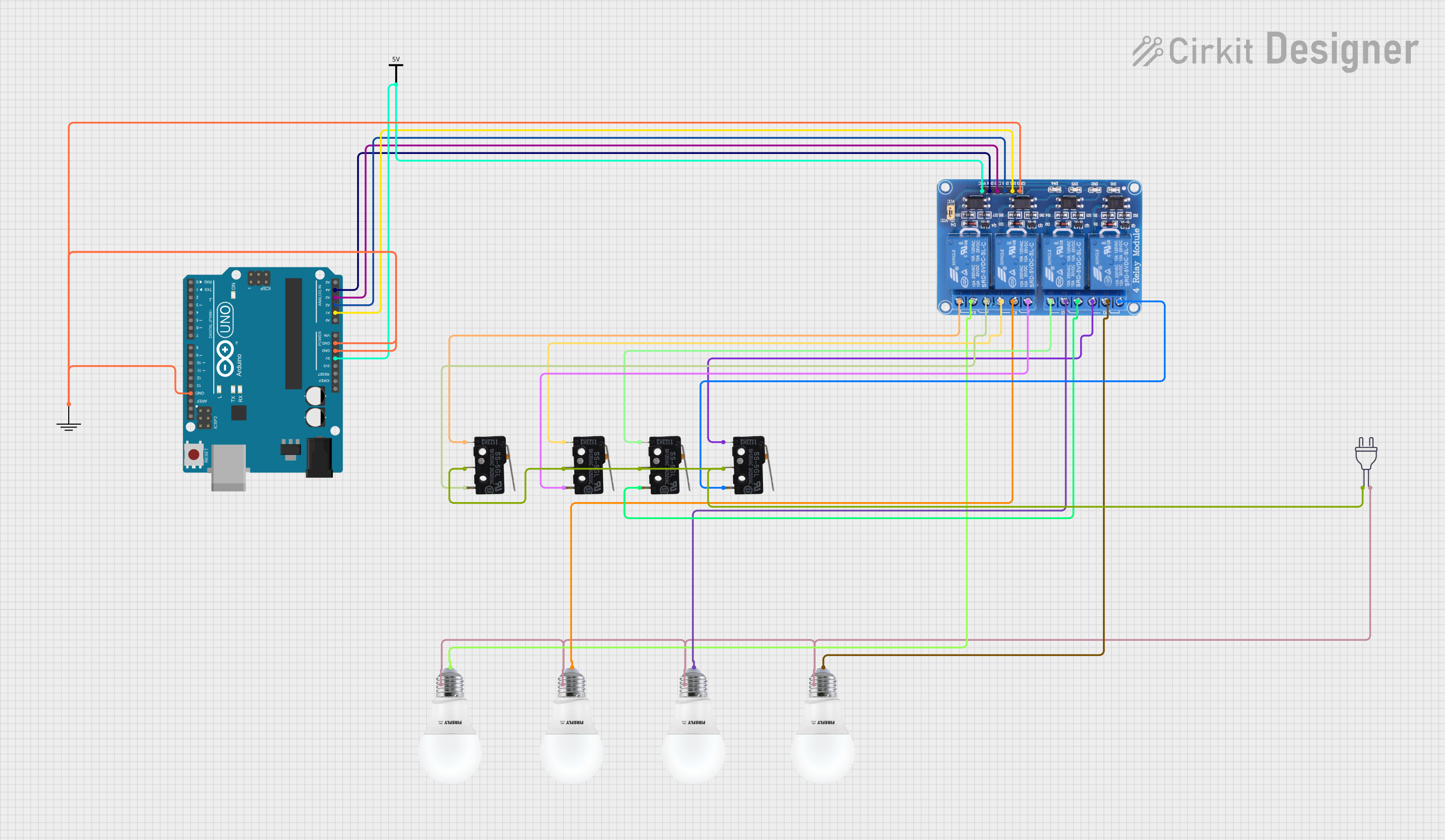
Example: Using the Module with an Arduino UNO
Below is an example of how to control the 4 Channel Relay Module using an Arduino UNO:
// Example: Controlling a 4 Channel Relay Module with Arduino UNO

// Define the relay control pins
#define RELAY1 2  // Relay 1 connected to digital pin 2
#define RELAY2 3  // Relay 2 connected to digital pin 3
#define RELAY3 4  // Relay 3 connected to digital pin 4
#define RELAY4 5  // Relay 4 connected to digital pin 5

void setup() {
  // Set relay pins as outputs
  pinMode(RELAY1, OUTPUT);
  pinMode(RELAY2, OUTPUT);
  pinMode(RELAY3, OUTPUT);
  pinMode(RELAY4, OUTPUT);

  // Initialize all relays to OFF (HIGH state)
  digitalWrite(RELAY1, HIGH);
  digitalWrite(RELAY2, HIGH);
  digitalWrite(RELAY3, HIGH);
  digitalWrite(RELAY4, HIGH);
}

void loop() {
  // Example sequence to toggle relays
  digitalWrite(RELAY1, LOW);  // Turn ON Relay 1
  delay(1000);                // Wait 1 second
  digitalWrite(RELAY1, HIGH); // Turn OFF Relay 1

  digitalWrite(RELAY2, LOW);  // Turn ON Relay 2
  delay(1000);                // Wait 1 second
  digitalWrite(RELAY2, HIGH); // Turn OFF Relay 2

  digitalWrite(RELAY3, LOW);  // Turn ON Relay 3
  delay(1000);                // Wait 1 second
  digitalWrite(RELAY3, HIGH); // Turn OFF Relay 3

  digitalWrite(RELAY4, LOW);  // Turn ON Relay 4
  delay(1000);                // Wait 1 second
  digitalWrite(RELAY4, HIGH); // Turn OFF Relay 4
}
Troubleshooting and FAQs
Common Issues and Solutions
Relays Not Activating:
- Cause: Insufficient power supply.
- Solution: Ensure the module is powered with a stable 5V DC source.
Microcontroller Not Triggering Relays:
- Cause: Incorrect wiring or logic level mismatch.
- Solution: Verify the control pins are connected properly and sending LOW signals to activate the relays.
Load Not Switching:
- Cause: Incorrect wiring of the load to the relay terminals.
- Solution: Double-check the connections to the COM, NO, and NC terminals.
Relay Clicking Noise but No Load Switching:
- Cause: Load exceeds the relay's maximum rating.
- Solution: Ensure the load is within the specified voltage and current limits.
FAQs
Q1: Can I use the module with a 3.3V microcontroller like ESP32?
A1: Yes, the module is compatible with 3.3V logic levels, but ensure the power supply to the module is 5V.
Q2: Can I control AC and DC loads simultaneously?
A2: Yes, as long as each relay's load does not exceed the specified ratings.
Q3: Is it safe to use the module for high-power devices?
A3: Yes, but always ensure proper insulation and follow safety guidelines when working with high voltages.