Cirkit Designer Logo
Cirkit Designer
Your all-in-one circuit design IDE
Home / 
Component Documentation

How to Use POWER SUPPLY: Examples, Pinouts, and Specs

Image of POWER SUPPLY
Cirkit Designer LogoDesign with POWER SUPPLY in Cirkit Designer

Introduction

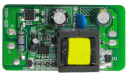
A power supply is an essential electronic component that provides electrical energy to a circuit. It converts AC or DC voltage from a source into a stable and usable form for powering electronic devices and components. The 12V 1A Power Supply is a compact and reliable device designed to deliver a constant 12V DC output with a maximum current of 1A. This makes it suitable for a wide range of low-power electronic applications.

Explore Projects Built with POWER SUPPLY

Use Cirkit Designer to design, explore, and prototype these projects online. Some projects support real-time simulation. Click "Open Project" to start designing instantly!
12V UPS System with Dual 18650 Li-ion Battery Backup and Voltage Regulation
Image of Power supply: A project utilizing POWER SUPPLY in a practical application
This circuit is designed to provide an uninterruptible power supply (UPS) system with a 12V DC output. It includes a 12V 5A power supply connected to an AC source through a toggle switch, which charges a pair of 18650 Li-ion batteries via a voltage regulator (XL4016). The UPS module ensures a continuous power supply to the load by switching between the power supply and the battery bank.
Cirkit Designer LogoOpen Project in Cirkit Designer
Dual 5V Power Supply Distribution Circuit with Toggle Switch Control
Image of rfdriver: A project utilizing POWER SUPPLY in a practical application
This circuit consists of two 5V 5A power supplies connected to an AC wall plug point, providing DC output through a 12-way connector. The ground connections from both power supplies are interconnected and also connected to the ground pins of two toggle switches. The DC outputs from the power supplies are separately connected to different pins on the 12-way connector, with each power supply output being switchable via one of the toggle switches.
Cirkit Designer LogoOpen Project in Cirkit Designer
AC to DC Power Supply with Transformer and Bridge Rectifier
Image of BRIDGE RECTIFIER: A project utilizing POWER SUPPLY in a practical application
This circuit is a basic AC to DC power supply that steps down 220V AC to a lower voltage using a transformer, rectifies it to DC using a bridge rectifier made of diodes, and smooths the output with an electrolytic capacitor. A rocker switch is used to turn the power supply on and off.
Cirkit Designer LogoOpen Project in Cirkit Designer
AC to DC Power Supply with Voltage Regulation and Overcurrent Protection
Image of PENGATUR VOLTAN: A project utilizing POWER SUPPLY in a practical application
This circuit appears to be a power supply unit with a transformer for stepping down voltage, a bridge rectifier for converting AC to DC, and a voltage regulator for stabilizing the output voltage. It includes a Zener diode for overvoltage protection, capacitors for smoothing out ripples in the DC supply, and a fuse for overcurrent protection. A toggle switch and a rocker switch are used to control the power flow, and there is an LED indicator connected through resistors, likely for power-on indication.
Cirkit Designer LogoOpen Project in Cirkit Designer

Explore Projects Built with POWER SUPPLY

Use Cirkit Designer to design, explore, and prototype these projects online. Some projects support real-time simulation. Click "Open Project" to start designing instantly!
Image of Power supply: A project utilizing POWER SUPPLY in a practical application
12V UPS System with Dual 18650 Li-ion Battery Backup and Voltage Regulation
This circuit is designed to provide an uninterruptible power supply (UPS) system with a 12V DC output. It includes a 12V 5A power supply connected to an AC source through a toggle switch, which charges a pair of 18650 Li-ion batteries via a voltage regulator (XL4016). The UPS module ensures a continuous power supply to the load by switching between the power supply and the battery bank.
Cirkit Designer LogoOpen Project in Cirkit Designer
Image of rfdriver: A project utilizing POWER SUPPLY in a practical application
Dual 5V Power Supply Distribution Circuit with Toggle Switch Control
This circuit consists of two 5V 5A power supplies connected to an AC wall plug point, providing DC output through a 12-way connector. The ground connections from both power supplies are interconnected and also connected to the ground pins of two toggle switches. The DC outputs from the power supplies are separately connected to different pins on the 12-way connector, with each power supply output being switchable via one of the toggle switches.
Cirkit Designer LogoOpen Project in Cirkit Designer
Image of BRIDGE RECTIFIER: A project utilizing POWER SUPPLY in a practical application
AC to DC Power Supply with Transformer and Bridge Rectifier
This circuit is a basic AC to DC power supply that steps down 220V AC to a lower voltage using a transformer, rectifies it to DC using a bridge rectifier made of diodes, and smooths the output with an electrolytic capacitor. A rocker switch is used to turn the power supply on and off.
Cirkit Designer LogoOpen Project in Cirkit Designer
Image of PENGATUR VOLTAN: A project utilizing POWER SUPPLY in a practical application
AC to DC Power Supply with Voltage Regulation and Overcurrent Protection
This circuit appears to be a power supply unit with a transformer for stepping down voltage, a bridge rectifier for converting AC to DC, and a voltage regulator for stabilizing the output voltage. It includes a Zener diode for overvoltage protection, capacitors for smoothing out ripples in the DC supply, and a fuse for overcurrent protection. A toggle switch and a rocker switch are used to control the power flow, and there is an LED indicator connected through resistors, likely for power-on indication.
Cirkit Designer LogoOpen Project in Cirkit Designer

Common Applications and Use Cases

  • Powering microcontrollers (e.g., Arduino, Raspberry Pi)
  • Driving small DC motors or actuators
  • Supplying power to LED strips or lighting systems
  • Charging small battery packs
  • General-purpose use in low-power electronic circuits

Technical Specifications

The following table outlines the key technical details of the 12V 1A Power Supply:

Parameter Specification
Input Voltage 100-240V AC, 50/60Hz
Output Voltage 12V DC
Maximum Output Current 1A
Power Rating 12W
Efficiency ≥ 80%
Connector Type Barrel Jack (5.5mm outer diameter, 2.1mm inner diameter)
Protection Features Overload, Short Circuit, Overvoltage

Pin Configuration and Descriptions

The 12V 1A Power Supply typically has two main connections:

Pin/Connector Description
Positive (+) Supplies the +12V DC output voltage
Negative (-) Ground (GND) connection for the circuit

Usage Instructions

How to Use the Component in a Circuit

  1. Connect the Power Supply to the Input Source:
    • Plug the power supply into a standard AC wall outlet (100-240V AC).
  2. Connect the Output to Your Circuit:
    • Use the barrel jack connector to connect the power supply to your circuit. Ensure the polarity matches: the center pin is positive (+), and the outer sleeve is negative (-).
  3. Verify Voltage and Current Requirements:
    • Ensure that the connected circuit operates at 12V DC and does not draw more than 1A of current. Exceeding these limits may damage the power supply or the connected device.

Important Considerations and Best Practices

  • Check Polarity: Always verify the polarity of the power supply output before connecting it to your circuit to avoid damage.
  • Avoid Overloading: Do not connect devices that require more than 1A of current, as this may cause the power supply to overheat or shut down.
  • Use Proper Connectors: Ensure a secure and reliable connection using compatible barrel jack connectors.
  • Ventilation: Place the power supply in a well-ventilated area to prevent overheating during operation.

Example: Using the Power Supply with an Arduino UNO

The 12V 1A Power Supply can be used to power an Arduino UNO via its DC barrel jack. Below is an example of how to connect and use it:

  1. Plug the power supply into a wall outlet.
  2. Connect the barrel jack output to the Arduino UNO's DC input port.
  3. Verify that the Arduino's onboard power LED lights up, indicating proper power delivery.

Sample Arduino Code

Here is a simple Arduino sketch to blink an LED while powered by the 12V 1A Power Supply:

// This code blinks an LED connected to pin 13 of the Arduino UNO.
// Ensure the Arduino is powered using the 12V 1A Power Supply.

void setup() {
  pinMode(13, OUTPUT); // Set pin 13 as an output
}

void loop() {
  digitalWrite(13, HIGH); // Turn the LED on
  delay(1000);            // Wait for 1 second
  digitalWrite(13, LOW);  // Turn the LED off
  delay(1000);            // Wait for 1 second
}

Troubleshooting and FAQs

Common Issues Users Might Face

  1. No Output Voltage:

    • Cause: The power supply is not properly connected to the AC source.
    • Solution: Check the AC input connection and ensure the wall outlet is functional.
  2. Device Not Powering On:

    • Cause: Incorrect polarity or loose connections.
    • Solution: Verify the polarity of the barrel jack and ensure a secure connection.
  3. Overheating:

    • Cause: The connected device is drawing more than 1A of current.
    • Solution: Reduce the load or use a power supply with a higher current rating.
  4. Intermittent Power Delivery:

    • Cause: Faulty or damaged connectors.
    • Solution: Inspect the barrel jack and replace it if necessary.

Solutions and Tips for Troubleshooting

  • Use a multimeter to measure the output voltage and confirm it is 12V DC.
  • If the power supply shuts down, disconnect the load and allow it to cool before reconnecting.
  • Ensure the power supply is not exposed to moisture or extreme temperatures during operation.

By following these guidelines and best practices, the 12V 1A Power Supply can be effectively used in a variety of electronic applications.