Cirkit Designer Logo
Cirkit Designer
Your all-in-one circuit design IDE
Home / 
Component Documentation

How to Use SIM28M GPS Module: Examples, Pinouts, and Specs

Image of SIM28M GPS Module
Cirkit Designer LogoDesign with SIM28M GPS Module in Cirkit Designer

Introduction

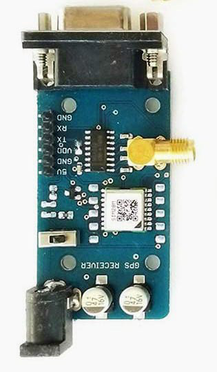
The SIM28M GPS Module is a compact and efficient GPS receiver that provides accurate location data by receiving signals from GPS satellites. This module is widely used in various applications such as navigation systems, tracking devices, and other projects requiring precise positioning. Its small form factor and ease of integration make it a popular choice among hobbyists and professionals alike.

Explore Projects Built with SIM28M GPS Module

Use Cirkit Designer to design, explore, and prototype these projects online. Some projects support real-time simulation. Click "Open Project" to start designing instantly!
Cellular-Enabled IoT Device with Real-Time Clock and Power Management
Image of LRCM PHASE 2 BASIC: A project utilizing SIM28M GPS Module in a practical application
This circuit features a LilyGo-SIM7000G module for cellular communication and GPS functionality, interfaced with an RTC DS3231 for real-time clock capabilities. It includes voltage sensing through two voltage sensor modules, and uses an 8-channel opto-coupler for isolating different parts of the circuit. Power management is handled by a buck converter connected to a DC power source and batteries, with a fuse for protection and a rocker switch for on/off control. Additionally, there's an LED for indication purposes.
Cirkit Designer LogoOpen Project in Cirkit Designer
Arduino Nano Based GPS Tracker with GSM Communication and Accelerometer
Image of Circuit Aayush: A project utilizing SIM28M GPS Module in a practical application
This circuit is designed for communication and location tracking purposes. It features an Arduino Nano interfaced with a SIM800L GSM module for cellular connectivity, a GPS NEO 6M module for obtaining geographical coordinates, and an AITrip ADXL335 GY-61 accelerometer for motion sensing. The LM2596 Step Down Module is used to regulate the power supply to the components.
Cirkit Designer LogoOpen Project in Cirkit Designer
ESP32-Based Cellular and GPS Tracking System with User Interface
Image of Keychain Device: A project utilizing SIM28M GPS Module in a practical application
This circuit features an ESP32 microcontroller interfaced with a SIM 800L GSM module for cellular communication and a Neo 6M GPS module for location tracking. A voltage regulator is used to maintain a stable voltage supply from a polymer lithium-ion battery to the GSM, GPS, and ESP32 modules. Additionally, the circuit includes a pushbutton to trigger inputs and an LED with a current-limiting resistor, likely for status indication.
Cirkit Designer LogoOpen Project in Cirkit Designer
Raspberry Pi Pico-Based Navigation Assistant with Bluetooth and GPS
Image of sat_dish: compass example: A project utilizing SIM28M GPS Module in a practical application
This circuit features a Raspberry Pi Pico microcontroller interfaced with an HC-05 Bluetooth module for wireless communication, an HMC5883L compass module for magnetic field measurement, and a GPS NEO 6M module for location tracking. The Pico is configured to communicate with the HC-05 via serial connection (TX/RX), with the compass module via I2C (SCL/SDA), and with the GPS module via serial (TX/RX). Common power (VCC) and ground (GND) lines are shared among all modules, indicating a unified power system.
Cirkit Designer LogoOpen Project in Cirkit Designer

Explore Projects Built with SIM28M GPS Module

Use Cirkit Designer to design, explore, and prototype these projects online. Some projects support real-time simulation. Click "Open Project" to start designing instantly!
Image of LRCM PHASE 2 BASIC: A project utilizing SIM28M GPS Module in a practical application
Cellular-Enabled IoT Device with Real-Time Clock and Power Management
This circuit features a LilyGo-SIM7000G module for cellular communication and GPS functionality, interfaced with an RTC DS3231 for real-time clock capabilities. It includes voltage sensing through two voltage sensor modules, and uses an 8-channel opto-coupler for isolating different parts of the circuit. Power management is handled by a buck converter connected to a DC power source and batteries, with a fuse for protection and a rocker switch for on/off control. Additionally, there's an LED for indication purposes.
Cirkit Designer LogoOpen Project in Cirkit Designer
Image of Circuit Aayush: A project utilizing SIM28M GPS Module in a practical application
Arduino Nano Based GPS Tracker with GSM Communication and Accelerometer
This circuit is designed for communication and location tracking purposes. It features an Arduino Nano interfaced with a SIM800L GSM module for cellular connectivity, a GPS NEO 6M module for obtaining geographical coordinates, and an AITrip ADXL335 GY-61 accelerometer for motion sensing. The LM2596 Step Down Module is used to regulate the power supply to the components.
Cirkit Designer LogoOpen Project in Cirkit Designer
Image of Keychain Device: A project utilizing SIM28M GPS Module in a practical application
ESP32-Based Cellular and GPS Tracking System with User Interface
This circuit features an ESP32 microcontroller interfaced with a SIM 800L GSM module for cellular communication and a Neo 6M GPS module for location tracking. A voltage regulator is used to maintain a stable voltage supply from a polymer lithium-ion battery to the GSM, GPS, and ESP32 modules. Additionally, the circuit includes a pushbutton to trigger inputs and an LED with a current-limiting resistor, likely for status indication.
Cirkit Designer LogoOpen Project in Cirkit Designer
Image of sat_dish: compass example: A project utilizing SIM28M GPS Module in a practical application
Raspberry Pi Pico-Based Navigation Assistant with Bluetooth and GPS
This circuit features a Raspberry Pi Pico microcontroller interfaced with an HC-05 Bluetooth module for wireless communication, an HMC5883L compass module for magnetic field measurement, and a GPS NEO 6M module for location tracking. The Pico is configured to communicate with the HC-05 via serial connection (TX/RX), with the compass module via I2C (SCL/SDA), and with the GPS module via serial (TX/RX). Common power (VCC) and ground (GND) lines are shared among all modules, indicating a unified power system.
Cirkit Designer LogoOpen Project in Cirkit Designer

Technical Specifications

Key Technical Details

Parameter Value
Supply Voltage 3.0V to 4.3V
Operating Current 30mA (typical)
Acquisition Time Cold Start: 35s, Hot Start: 1s
Position Accuracy < 2.5m CEP
Velocity Accuracy 0.1 m/s
Update Rate 1Hz
Operating Temperature -40°C to +85°C
Dimensions 16mm x 16mm x 6.2mm

Pin Configuration and Descriptions

Pin Number Pin Name Description
1 VCC Power supply (3.0V to 4.3V)
2 GND Ground
3 TXD UART Transmit Data
4 RXD UART Receive Data
5 PPS Pulse Per Second (1Hz output)
6 EN Enable (Active High)
7 NC Not Connected
8 NC Not Connected

Usage Instructions

How to Use the SIM28M GPS Module in a Circuit

  1. Power Supply: Connect the VCC pin to a 3.0V to 4.3V power supply and the GND pin to the ground of your circuit.
  2. UART Communication: Connect the TXD pin to the RX pin of your microcontroller (e.g., Arduino UNO) and the RXD pin to the TX pin of your microcontroller.
  3. Enable Pin: Connect the EN pin to a high logic level (3.3V or 5V) to enable the module.
  4. PPS Output: The PPS pin provides a 1Hz pulse that can be used for precise timing applications.

Important Considerations and Best Practices

  • Antenna: Ensure that the module is connected to a suitable GPS antenna for optimal signal reception.
  • Placement: Place the module in an open area with a clear view of the sky to improve satellite acquisition and accuracy.
  • Power Supply: Use a stable power supply to avoid fluctuations that could affect the module's performance.
  • UART Settings: Configure the UART communication settings (baud rate, data bits, parity, stop bits) according to the module's specifications.

Example Code for Arduino UNO

#include <SoftwareSerial.h>

// Create a software serial port on pins 4 (RX) and 3 (TX)
SoftwareSerial gpsSerial(4, 3);

void setup() {
  // Start the hardware serial port for communication with the PC
  Serial.begin(9600);
  // Start the software serial port for communication with the GPS module
  gpsSerial.begin(9600);
}

void loop() {
  // Check if data is available from the GPS module
  if (gpsSerial.available()) {
    // Read data from the GPS module
    char c = gpsSerial.read();
    // Print the data to the serial monitor
    Serial.print(c);
  }
}

Troubleshooting and FAQs

Common Issues and Solutions

  1. No GPS Fix:

    • Solution: Ensure the module has a clear view of the sky and is connected to a suitable antenna. Check the power supply and connections.
  2. No Data Output:

    • Solution: Verify the UART connections and ensure the baud rate settings match between the GPS module and the microcontroller.
  3. Intermittent Data:

    • Solution: Check for power supply stability and ensure the antenna is properly connected and positioned.

FAQs

Q1: What type of antenna should I use with the SIM28M GPS Module?

  • A1: Use a GPS antenna with a 1575.42 MHz frequency for optimal performance.

Q2: Can I use the SIM28M GPS Module indoors?

  • A2: The module is designed for outdoor use with a clear view of the sky. Indoor use may result in poor signal reception and accuracy.

Q3: How do I improve the acquisition time of the GPS module?

  • A3: Ensure the module has a clear view of the sky and is connected to a high-quality antenna. A stable power supply also helps improve acquisition time.

Q4: What is the purpose of the PPS pin?

  • A4: The PPS (Pulse Per Second) pin provides a precise 1Hz pulse that can be used for timing applications requiring high accuracy.

By following this documentation, users can effectively integrate and utilize the SIM28M GPS Module in their projects, ensuring accurate and reliable GPS data.