How to Use LilyPad Accelerometer: Examples, Pinouts, and Specs
Introduction
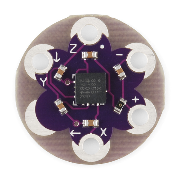
The LilyPad Accelerometer ADXL335 is a small, thin, low-power, complete 3-axis accelerometer with signal-conditioned voltage outputs. It measures acceleration with a minimum full-scale range of ±3 g. It can measure the static acceleration of gravity in tilt-sensing applications, as well as dynamic acceleration resulting from motion or shock. Its high resolution (1 mg/LSB) enables the measurement of inclination changes less than 1.0°.
Common applications of the LilyPad Accelerometer include:
- Wearable devices
- Motion detection
- Gaming and pointing devices
- Fitness and activity monitoring
- Tilt sensing in robotics and vehicles
Explore Projects Built with LilyPad Accelerometer
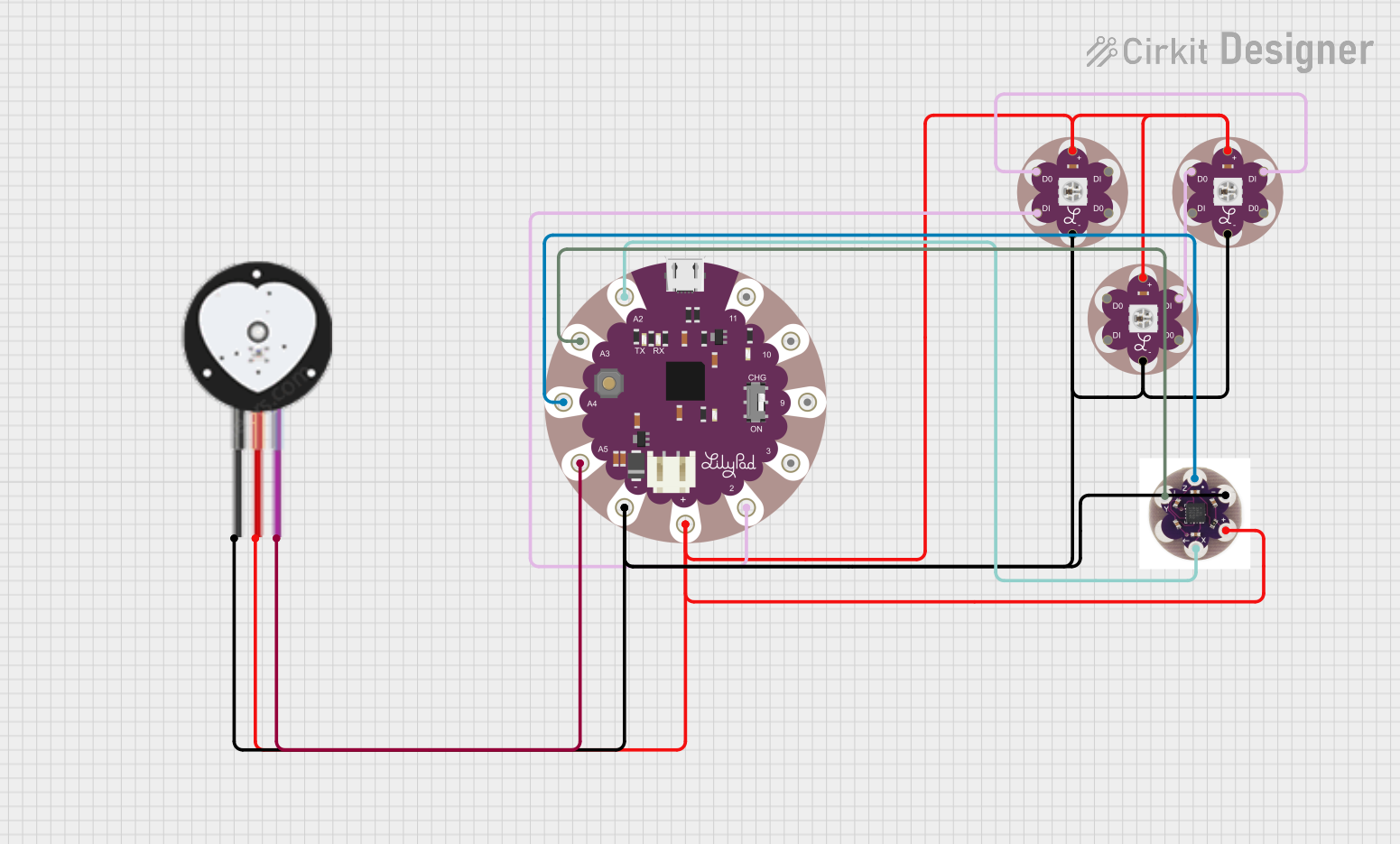
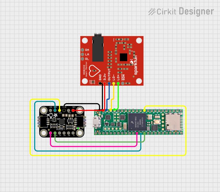

Explore Projects Built with LilyPad Accelerometer
Technical Specifications
Key Technical Details
- Power Supply: 2.0V to 3.6V DC
- Sensitivity: Typically 300 mV/g at 3V
- Measurement Range: ±3 g
- Bandwidth: 50 Hz
- Operating Temperature: -40°C to +85°C
- Self-Test Feature
Pin Configuration and Descriptions
| Pin Label | Description |
|---|---|
| X-OUT | X-axis output voltage |
| Y-OUT | Y-axis output voltage |
| Z-OUT | Z-axis output voltage |
| VCC | Power supply (2.0V to 3.6V) |
| GND | Ground |
| ST | Self-test (activated by logic high input) |
Usage Instructions
Integration with a Circuit
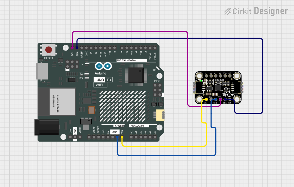
To use the LilyPad Accelerometer in a circuit:
- Connect the VCC pin to a power supply between 2.0V and 3.6V.
- Connect the GND pin to the ground of the power supply.
- The X-OUT, Y-OUT, and Z-OUT pins provide analog voltage outputs that correspond to the acceleration on each axis. Connect these to analog inputs on your microcontroller, such as an Arduino UNO.
Best Practices
- Ensure that the power supply voltage does not exceed 3.6V.
- Use capacitors for noise reduction if necessary, as specified in the datasheet.
- Avoid physical shock and vibration that exceed the specified limits.
- Keep the device within the specified temperature range to ensure accuracy.
Example Code for Arduino UNO
// Include the Arduino core library
#include <Arduino.h>

// Define the analog pins connected to the accelerometer
const int xPin = A0;
const int yPin = A1;
const int zPin = A2;

void setup() {
  // Initialize the serial communication
  Serial.begin(9600);
}

void loop() {
  // Read the analog values from the accelerometer
  int xValue = analogRead(xPin);
  int yValue = analogRead(yPin);
  int zValue = analogRead(zPin);

  // Convert the analog values to acceleration in g's
  float xAccel = (xValue - 338.0) / 100.0; // 338 is zero-g voltage for x-axis
  float yAccel = (yValue - 338.0) / 100.0; // 338 is zero-g voltage for y-axis
  float zAccel = (zValue - 338.0) / 100.0; // 338 is zero-g voltage for z-axis

  // Print the acceleration values to the serial monitor
  Serial.print("X: ");
  Serial.print(xAccel);
  Serial.print("g, Y: ");
  Serial.print(yAccel);
  Serial.print("g, Z: ");
  Serial.print(zAccel);
  Serial.println("g");

  // Delay before the next reading
  delay(100);
}
Note: The zero-g voltage and sensitivity may vary slightly from one device to another. Calibration may be required for precise measurements.
Troubleshooting and FAQs
Common Issues
- Inaccurate Readings: Ensure that the accelerometer is properly calibrated. Check for any power supply issues or interference from other electronic components.
- No Output Signal: Verify that the VCC and GND connections are secure and that the power supply is within the specified range.
- Intermittent Signal: Check for loose connections and ensure that the accelerometer is not subjected to mechanical stress or shock beyond its limits.
FAQs
Q: Can the LilyPad Accelerometer be washed? A: The LilyPad Accelerometer is designed for use in e-textiles and wearable projects, but it is not waterproof. It should be removed before washing the fabric.
Q: How do I calibrate the accelerometer? A: Calibration involves recording the output at known orientations and adjusting the readings accordingly. Refer to the datasheet for detailed calibration procedures.
Q: What is the purpose of the self-test pin? A: The self-test pin, when set to a logic high, allows you to check the functionality of the accelerometer by producing a known output signal.
For further assistance, consult the manufacturer's datasheet and technical support resources.