Cirkit Designer Logo
Cirkit Designer
Your all-in-one circuit design IDE
Home / 
Component Documentation

How to Use MCP73831: Examples, Pinouts, and Specs

Image of MCP73831
Cirkit Designer LogoDesign with MCP73831 in Cirkit Designer

Introduction

The MCP73831 is a highly integrated linear charge management controller for single-cell Lithium-Ion and Lithium-Polymer batteries. It is designed for space-limited and cost-sensitive applications, providing a simple and efficient solution for charging Li-ion/Li-Po batteries. The MCP73831 integrates current regulation, voltage regulation, charge termination, and charge status indication, making it ideal for portable electronics, such as smartphones, cameras, and personal media players.

Explore Projects Built with MCP73831

Use Cirkit Designer to design, explore, and prototype these projects online. Some projects support real-time simulation. Click "Open Project" to start designing instantly!
ESP32-Based Vibration Motor Controller with I2C IO Expansion
Image of VIBRATYION: A project utilizing MCP73831 in a practical application
This circuit features an ESP32 Wroom Dev Kit microcontroller interfaced with an MCP23017 I/O expansion board via I2C communication, utilizing GPIO 21 and GPIO 22 for SDA and SCL lines, respectively. A vibration motor is controlled by an NPN transistor acting as a switch, with a diode for back EMF protection and a resistor to limit base current. The ESP32 can control the motor by sending signals to the MCP23017, which then interfaces with the transistor to turn the motor on or off.
Cirkit Designer LogoOpen Project in Cirkit Designer
ESP32-Based I2C Communication Hub with Multiplexer and Expander
Image of Lights: A project utilizing MCP73831 in a practical application
This circuit features an Olimex ESP32-EVB microcontroller unit (MCU) for processing and connectivity, interfaced with an MCP23017 I/O expander and an Adafruit TCA9548A I2C multiplexer to expand the number of I/O lines and allow multiple I2C devices to communicate with the MCU over the same bus. Pull-up resistors are connected to the I2C lines for proper bus operation, and both the MCP23017 and TCA9548A have their reset lines pulled high, likely for normal operation without external reset control.
Cirkit Designer LogoOpen Project in Cirkit Designer
I2C-Controlled Relay Switching with ESP32 and MCP23017 for Home Automation
Image of Vloerverwarming: A project utilizing MCP73831 in a practical application
This circuit appears to be a control system utilizing two MCP23017 I/O expanders interfaced with an Olimex ESP32-EVB microcontroller via I2C communication, as indicated by the SDA and SCL connections with pull-up resistors. The MCP23017 expanders control an 8-channel relay module, allowing the microcontroller to switch various loads, potentially for home automation or industrial control. Additionally, there is an Adafruit ADS1115 16-bit ADC for analog signal measurement, and several heating actuators and a thermostat are connected, suggesting temperature control functionality.
Cirkit Designer LogoOpen Project in Cirkit Designer
MCP23017-Expanded I/O Interface with ADS1115 ADC and ESP32 Control
Image of door and window sensors: A project utilizing MCP73831 in a practical application
This circuit features two MCP23017 I/O expanders interfaced with multiple switches, allowing for the expansion of input capabilities. The MCP23017s are connected via I2C to an Olimex ESP32-EVB microcontroller, which likely manages the input states from the switches. Additionally, an Adafruit ADS1115 16-bit ADC is included, suggesting that some analog inputs are being monitored, with the ADC also interfaced with the ESP32 via I2C.
Cirkit Designer LogoOpen Project in Cirkit Designer

Explore Projects Built with MCP73831

Use Cirkit Designer to design, explore, and prototype these projects online. Some projects support real-time simulation. Click "Open Project" to start designing instantly!
Image of VIBRATYION: A project utilizing MCP73831 in a practical application
ESP32-Based Vibration Motor Controller with I2C IO Expansion
This circuit features an ESP32 Wroom Dev Kit microcontroller interfaced with an MCP23017 I/O expansion board via I2C communication, utilizing GPIO 21 and GPIO 22 for SDA and SCL lines, respectively. A vibration motor is controlled by an NPN transistor acting as a switch, with a diode for back EMF protection and a resistor to limit base current. The ESP32 can control the motor by sending signals to the MCP23017, which then interfaces with the transistor to turn the motor on or off.
Cirkit Designer LogoOpen Project in Cirkit Designer
Image of Lights: A project utilizing MCP73831 in a practical application
ESP32-Based I2C Communication Hub with Multiplexer and Expander
This circuit features an Olimex ESP32-EVB microcontroller unit (MCU) for processing and connectivity, interfaced with an MCP23017 I/O expander and an Adafruit TCA9548A I2C multiplexer to expand the number of I/O lines and allow multiple I2C devices to communicate with the MCU over the same bus. Pull-up resistors are connected to the I2C lines for proper bus operation, and both the MCP23017 and TCA9548A have their reset lines pulled high, likely for normal operation without external reset control.
Cirkit Designer LogoOpen Project in Cirkit Designer
Image of Vloerverwarming: A project utilizing MCP73831 in a practical application
I2C-Controlled Relay Switching with ESP32 and MCP23017 for Home Automation
This circuit appears to be a control system utilizing two MCP23017 I/O expanders interfaced with an Olimex ESP32-EVB microcontroller via I2C communication, as indicated by the SDA and SCL connections with pull-up resistors. The MCP23017 expanders control an 8-channel relay module, allowing the microcontroller to switch various loads, potentially for home automation or industrial control. Additionally, there is an Adafruit ADS1115 16-bit ADC for analog signal measurement, and several heating actuators and a thermostat are connected, suggesting temperature control functionality.
Cirkit Designer LogoOpen Project in Cirkit Designer
Image of door and window sensors: A project utilizing MCP73831 in a practical application
MCP23017-Expanded I/O Interface with ADS1115 ADC and ESP32 Control
This circuit features two MCP23017 I/O expanders interfaced with multiple switches, allowing for the expansion of input capabilities. The MCP23017s are connected via I2C to an Olimex ESP32-EVB microcontroller, which likely manages the input states from the switches. Additionally, an Adafruit ADS1115 16-bit ADC is included, suggesting that some analog inputs are being monitored, with the ADC also interfaced with the ESP32 via I2C.
Cirkit Designer LogoOpen Project in Cirkit Designer

Common Applications and Use Cases

  • Portable electronic devices
  • Wearable technology
  • Bluetooth headsets and accessories
  • Health and fitness monitors
  • Backup power and energy storage solutions

Technical Specifications

Key Technical Details

  • Charge Regulation Voltage: 4.2V
  • Programmable Charge Current: 15mA to 500mA
  • Input Voltage Range: 3.75V to 6.0V
  • Operating Temperature Range: -40°C to +85°C
  • Charge Status Output: Active High

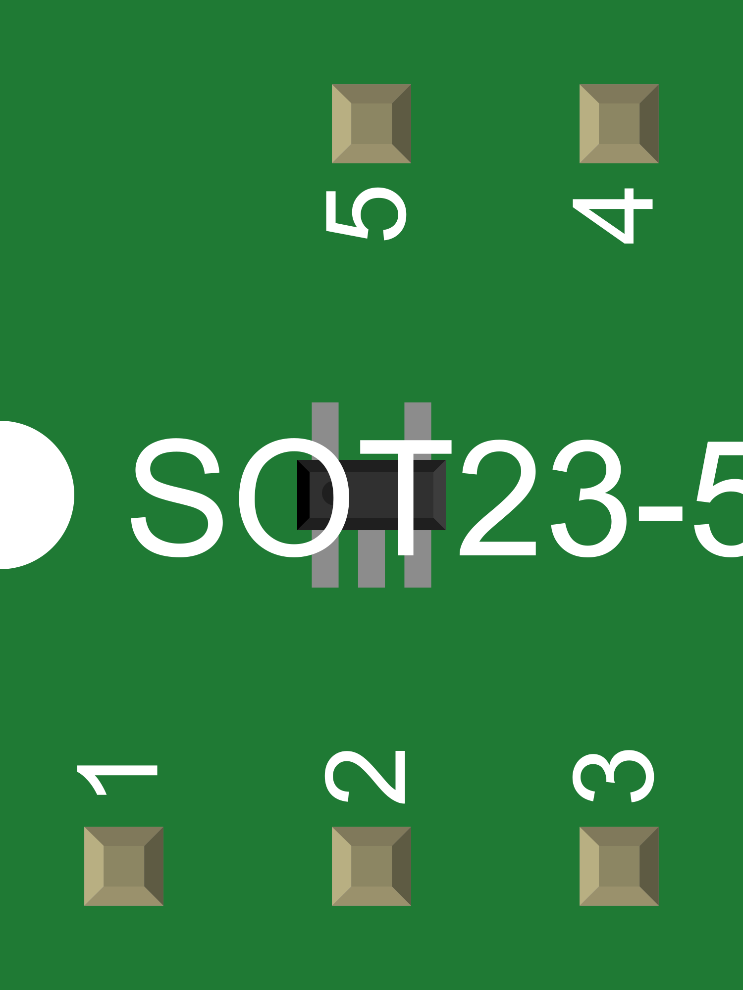
Pin Configuration and Descriptions

Pin Number Name Description
1 STAT Charge Status Output. Active high during charge cycle.
2 VSS Ground (0V) reference.
3 VBAT Connection to the positive terminal of the battery.
4 VDD Input supply voltage for the charge controller.
5 PROG Charge current programming pin. Connect a resistor to GND to set the charge current.

Usage Instructions

How to Use the MCP73831 in a Circuit

  1. Power Supply Connection: Connect a stable voltage source within the input voltage range (3.75V to 6.0V) to the VDD pin.
  2. Battery Connection: Connect the positive terminal of the Li-ion/Li-Po battery to the VBAT pin.
  3. Ground Connection: Connect the VSS pin to the ground of your power supply and battery.
  4. Charge Current Setting: Connect a resistor from the PROG pin to ground to set the desired charge current. Use the formula I_charge = 1000V / R_PROG to calculate the resistor value.
  5. Charge Status Indicator: The STAT pin can be connected to an LED with a current-limiting resistor to indicate the charging status or directly interfaced with a microcontroller.

Important Considerations and Best Practices

  • Ensure the power supply voltage does not exceed the maximum input voltage rating.
  • Use a stable power source to avoid fluctuations that could affect the charging process.
  • Select a charge current that is safe for your specific battery's charging specifications.
  • Avoid placing the MCP73831 in environments that exceed its temperature specifications.
  • Ensure proper thermal management to prevent overheating during operation.

Troubleshooting and FAQs

Common Issues Users Might Face

  • Battery Not Charging: Check the connections to the battery and ensure the input power supply is within the specified range.
  • Overheating: Ensure the charge current is not set too high for the battery or the MCP73831's thermal limits.
  • No Charge Status Indicator: Verify the STAT pin connection and the functionality of the charge status indicator circuit.

Solutions and Tips for Troubleshooting

  • Double-check all connections, especially the PROG resistor value and its soldering.
  • Measure the input voltage and the voltage at the VBAT pin to ensure proper levels.
  • If using an LED for charge status, confirm the LED and current-limiting resistor are correctly oriented and functioning.

FAQs

Q: Can I charge a battery with a higher voltage than 4.2V using the MCP73831? A: No, the MCP73831 is designed for single-cell Li-ion/Li-Po batteries with a charge regulation voltage of 4.2V.

Q: How do I know if the battery is fully charged? A: The STAT pin will be deasserted (logic low) when the battery is fully charged.

Q: Can I use the MCP73831 to charge multiple batteries in series? A: No, the MCP73831 is intended for single-cell battery charging only.

Q: What should I do if the MCP73831 is getting too hot during operation? A: Check the charge current setting and ensure it is within the recommended range for both the battery and the MCP73831. Also, improve heat dissipation with proper PCB layout and possibly a heat sink.

Example Code for Arduino UNO

// Example code to monitor the charge status of a battery using MCP73831 and Arduino UNO

const int chargeStatusPin = 2; // Connect the STAT pin of MCP73831 to digital pin 2

void setup() {
  pinMode(chargeStatusPin, INPUT);
  Serial.begin(9600);
}

void loop() {
  int chargeStatus = digitalRead(chargeStatusPin);
  
  // Check if the battery is currently charging
  if (chargeStatus == HIGH) {
    Serial.println("Battery is charging...");
  } else {
    Serial.println("Battery is fully charged or not charging.");
  }
  
  delay(1000); // Wait for 1 second before checking again
}

This code sets up the Arduino to read the charge status from the MCP73831 and print a message to the Serial Monitor indicating whether the battery is charging or fully charged. Make sure to connect the STAT pin of the MCP73831 to digital pin 2 on the Arduino UNO.