How to Use C25XP - Ethernet Smooth Stepper Integrated board: Examples, Pinouts, and Specs
Introduction
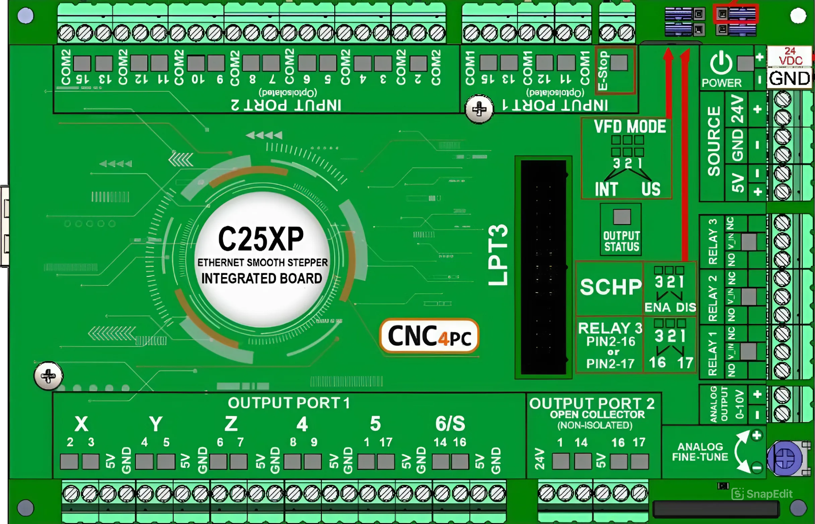
The C25XP - Ethernet Smooth Stepper Integrated Board (Manufacturer Part ID: C25XP V4.1) is a high-performance motion control board designed for CNC applications. Manufactured by CNC4PC, this board integrates Ethernet connectivity to enable high-speed communication and precise control of stepper motors. It is ideal for multi-axis systems, offering advanced features that simplify setup and enhance motion control accuracy.
Explore Projects Built with C25XP - Ethernet Smooth Stepper Integrated board

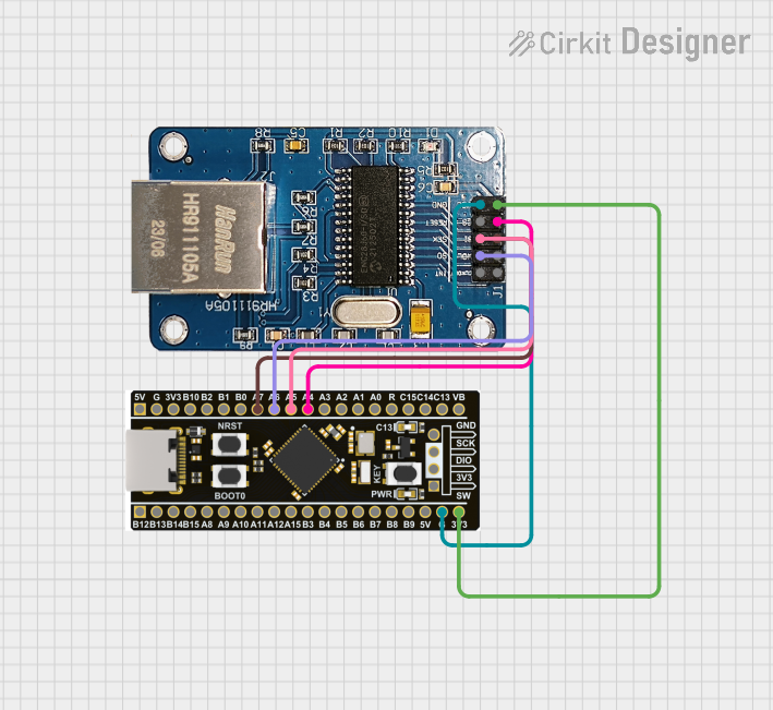
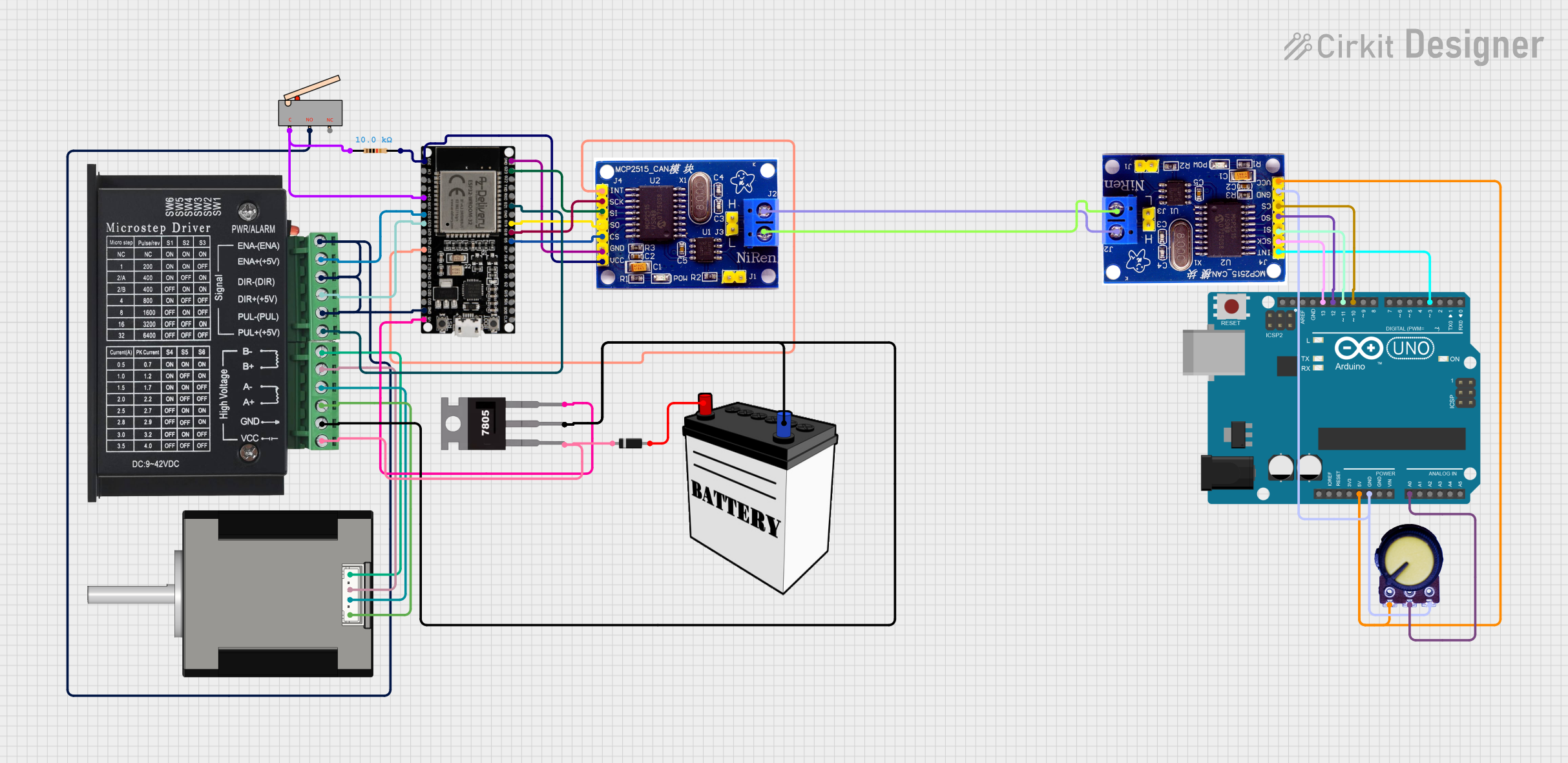
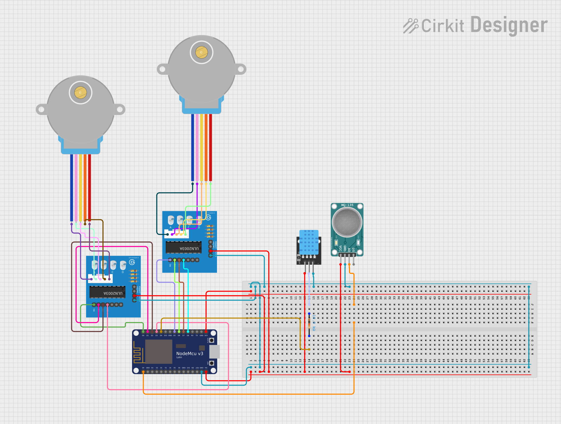
Explore Projects Built with C25XP - Ethernet Smooth Stepper Integrated board
Common Applications and Use Cases
- CNC routers, mills, lathes, and plasma cutters
- Multi-axis motion control systems
- Industrial automation requiring precise stepper motor control
- Retrofitting older CNC machines with modern motion control capabilities
- Applications requiring Ethernet-based communication for real-time control
Technical Specifications
Key Technical Details
| Parameter | Specification |
|---|---|
| Manufacturer | CNC4PC |
| Model | C25XP V4.1 |
| Communication Interface | Ethernet (10/100 Mbps) |
| Power Supply Input | 5V DC (via external power supply) |
| Stepper Motor Outputs | Up to 6 axes (X, Y, Z, A, B, C) |
| Input Voltage Range | 5V TTL logic for inputs |
| Output Voltage Range | 5V TTL logic for outputs |
| Maximum Step Frequency | 4 MHz |
| Dimensions | 4.5" x 3.5" (114mm x 89mm) |
| Operating Temperature | 0°C to 50°C |
| Mounting | DIN rail or panel mount |
Pin Configuration and Descriptions
The C25XP board features multiple connectors for stepper motor control, inputs, outputs, and power. Below is the pin configuration:
Stepper Motor Outputs
| Pin | Description |
|---|---|
| X+ | Step signal for X-axis |
| X- | Direction signal for X-axis |
| Y+ | Step signal for Y-axis |
| Y- | Direction signal for Y-axis |
| Z+ | Step signal for Z-axis |
| Z- | Direction signal for Z-axis |
| A+ | Step signal for A-axis |
| A- | Direction signal for A-axis |
| B+ | Step signal for B-axis |
| B- | Direction signal for B-axis |
| C+ | Step signal for C-axis |
| C- | Direction signal for C-axis |
Input/Output Pins
| Pin | Description |
|---|---|
| IN1 | General-purpose input 1 |
| IN2 | General-purpose input 2 |
| IN3 | General-purpose input 3 |
| IN4 | General-purpose input 4 |
| OUT1 | General-purpose output 1 |
| OUT2 | General-purpose output 2 |
| OUT3 | General-purpose output 3 |
| OUT4 | General-purpose output 4 |
Power and Communication
| Pin | Description |
|---|---|
| +5V | 5V DC power input |
| GND | Ground |
| ETH | Ethernet communication port |
Usage Instructions
How to Use the C25XP in a Circuit
- Power Supply: Connect a regulated 5V DC power supply to the
+5VandGNDpins. Ensure the power supply can provide sufficient current for the board and connected devices. - Ethernet Connection: Use a standard Ethernet cable to connect the C25XP to your PC or network. Configure the IP address of the board using the provided software or manual.
- Stepper Motor Connections: Connect the step and direction signals for each axis to the corresponding pins (e.g.,
X+,X-, etc.). Ensure proper wiring to avoid damage to the motors or board. - Inputs and Outputs: Wire sensors, switches, or other devices to the input pins (
IN1,IN2, etc.) and connect actuators or indicators to the output pins (OUT1,OUT2, etc.). - Software Configuration: Install the required motion control software (e.g., Mach3 or Mach4) on your PC. Configure the software to communicate with the C25XP via Ethernet and set up the pin mappings for your specific application.
Important Considerations and Best Practices
- Use shielded cables for stepper motor connections to minimize electromagnetic interference (EMI).
- Ensure proper grounding of the board and connected devices to avoid noise issues.
- Verify the stepper motor driver compatibility with the C25XP's 5V TTL logic signals.
- Avoid exceeding the maximum step frequency of 4 MHz to ensure reliable operation.
- Regularly update the firmware and software to benefit from the latest features and bug fixes.
Example Code for Arduino UNO Integration
Although the C25XP is primarily designed for CNC applications, it can be interfaced with an Arduino UNO for custom control. Below is an example of how to send step and direction signals to the X-axis:
// Define pins for step and direction signals
const int stepPin = 2;  // Step signal for X-axis
const int dirPin = 3;   // Direction signal for X-axis

void setup() {
  // Set step and direction pins as outputs
  pinMode(stepPin, OUTPUT);
  pinMode(dirPin, OUTPUT);

  // Set initial direction
  digitalWrite(dirPin, HIGH); // HIGH = forward, LOW = reverse
}

void loop() {
  // Generate step pulses
  digitalWrite(stepPin, HIGH); // Set step pin HIGH
  delayMicroseconds(500);      // Wait 500 microseconds
  digitalWrite(stepPin, LOW);  // Set step pin LOW
  delayMicroseconds(500);      // Wait 500 microseconds
}
Note: Ensure the Arduino's 5V logic levels are compatible with the C25XP's inputs. Use level shifters if necessary.
Troubleshooting and FAQs
Common Issues and Solutions
No Communication with the Board
- Cause: Incorrect Ethernet configuration or cable issue.
- Solution: Verify the Ethernet cable connection and ensure the PC and board are on the same network. Check the IP address settings in the software.
Stepper Motors Not Moving
- Cause: Incorrect wiring or configuration.
- Solution: Double-check the step and direction signal connections. Ensure the motor drivers are powered and configured correctly.
Inputs or Outputs Not Responding
- Cause: Faulty wiring or incorrect software configuration.
- Solution: Test the input/output pins with a multimeter. Verify the pin mappings in the software.
Excessive Noise or EMI
- Cause: Unshielded cables or poor grounding.
- Solution: Use shielded cables and ensure proper grounding of all components.
FAQs
Q: Can the C25XP control servo motors?
A: The C25XP is designed for stepper motors. However, it can interface with servo motor drivers that accept step and direction signals.Q: Is the C25XP compatible with Mach4?
A: Yes, the C25XP is fully compatible with both Mach3 and Mach4 software.Q: What is the maximum cable length for Ethernet communication?
A: The maximum recommended cable length is 100 meters (328 feet) for standard Ethernet.Q: Can I use the C25XP with a USB-to-Ethernet adapter?
A: Yes, but ensure the adapter is reliable and does not introduce latency.
By following this documentation, users can effectively integrate and operate the C25XP in their CNC or motion control systems.