How to Use EPW6 2.4GHz ELRS PWM Receiver: Examples, Pinouts, and Specs
Introduction
The EPW6 2.4GHz ELRS PWM Receiver by Happy Model is a compact and versatile receiver designed for remote control systems. It operates at a 2.4GHz frequency and leverages the ExpressLRS (ELRS) protocol, known for its low-latency and long-range communication capabilities. The EPW6 outputs PWM (Pulse Width Modulation) signals, making it ideal for controlling servos, electronic speed controllers (ESCs), and other devices in RC planes, drones, and robotics.
Explore Projects Built with EPW6 2.4GHz ELRS PWM Receiver
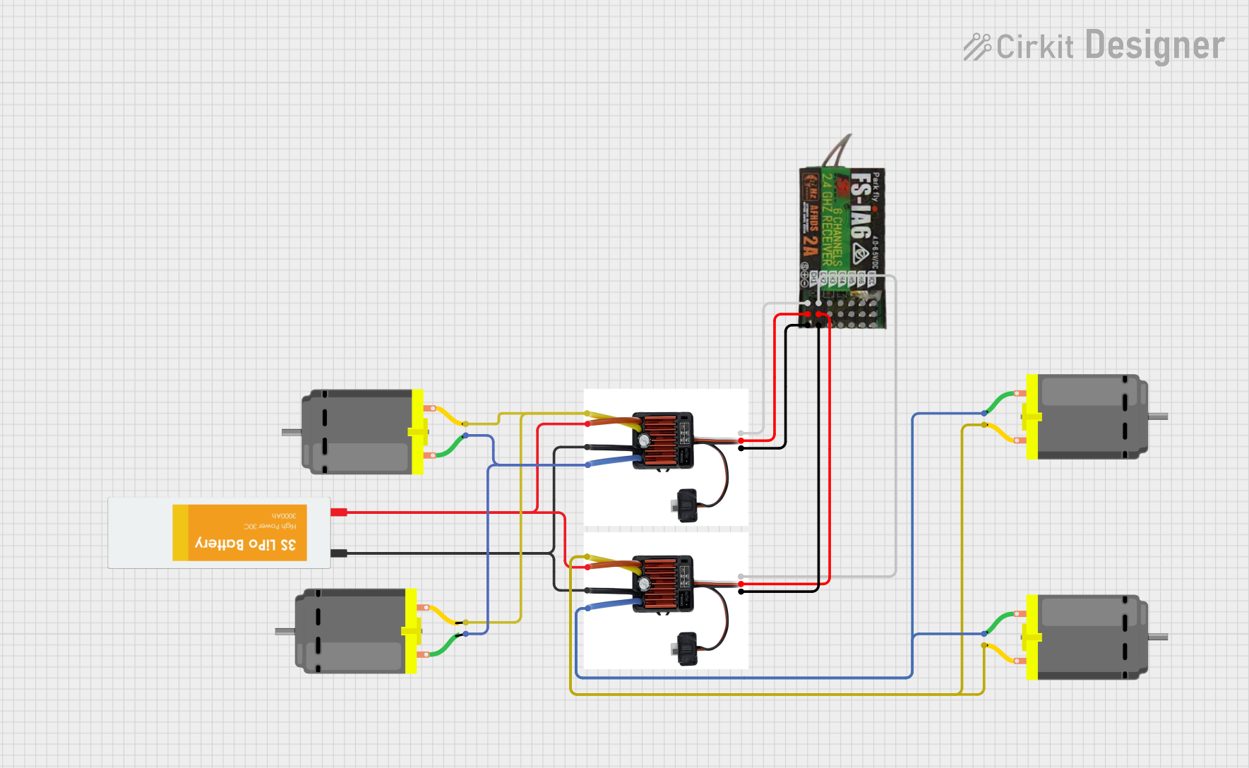
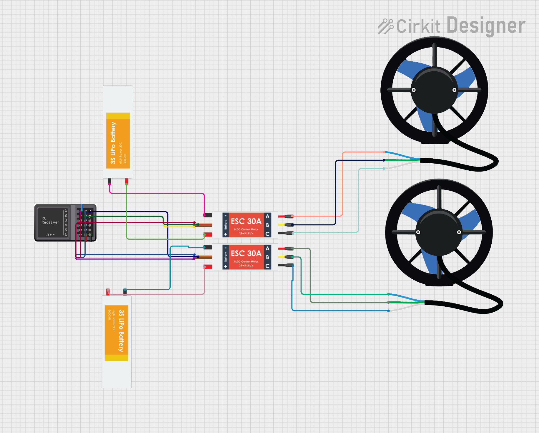
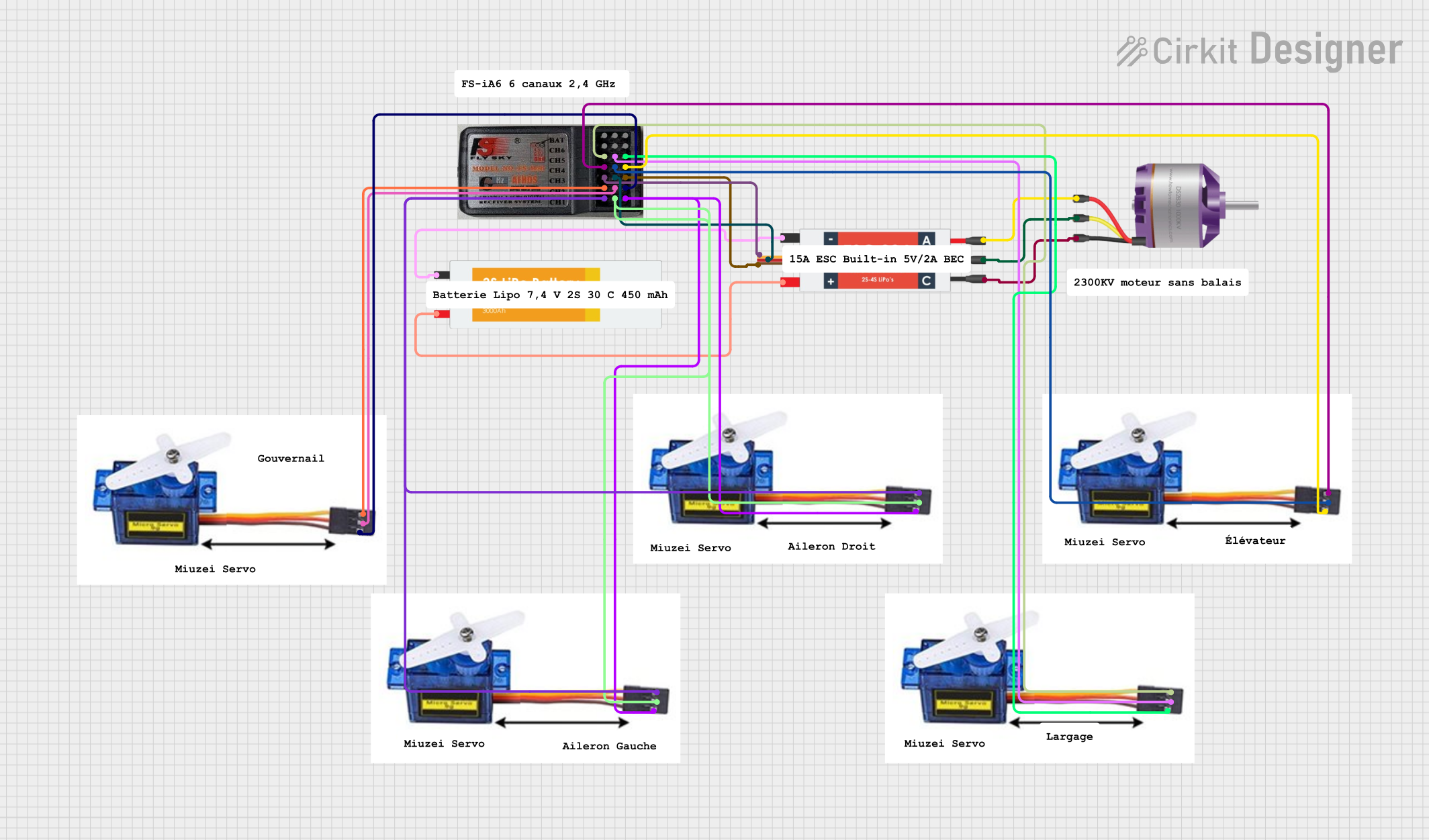
Explore Projects Built with EPW6 2.4GHz ELRS PWM Receiver
Common Applications
- RC Aircraft: Control servos and ESCs in fixed-wing planes and helicopters.
- Drones: Provide reliable communication for quadcopters and other UAVs.
- Robotics: Interface with motors and actuators in robotic systems.
- DIY Projects: Suitable for hobbyists building custom remote-controlled devices.
Technical Specifications
The following table outlines the key technical details of the EPW6 receiver:
| Parameter | Specification |
|---|---|
| Operating Frequency | 2.4GHz |
| Protocol | ExpressLRS (ELRS) |
| Input Voltage Range | 5V - 10V |
| Output Signal Type | PWM (6 channels) |
| Latency | Ultra-low (as low as 4ms, depending on ELRS settings) |
| Dimensions | 20mm x 15mm x 5mm |
| Weight | 2 grams |
| Antenna Type | Integrated ceramic antenna |
| Binding Method | ELRS binding phrase or manual binding |
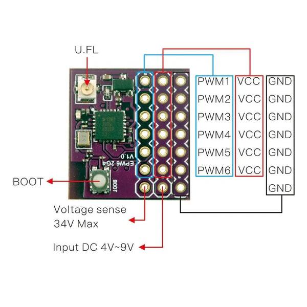
Pin Configuration and Descriptions
The EPW6 receiver has a 7-pin header for power and signal connections. The pinout is as follows:
| Pin Number | Label | Description |
|---|---|---|
| 1 | GND | Ground connection |
| 2 | VCC | Power input (5V - 10V) |
| 3 | CH1 | PWM output for Channel 1 |
| 4 | CH2 | PWM output for Channel 2 |
| 5 | CH3 | PWM output for Channel 3 |
| 6 | CH4 | PWM output for Channel 4 |
| 7 | CH5/CH6 | Combined PWM output for Channels 5 and 6 |
Note: Channels 5 and 6 share a single pin. The signal alternates based on the configuration in the ELRS transmitter.
Usage Instructions
Connecting the EPW6 Receiver
- Power Supply: Connect the VCC pin to a 5V-10V power source and the GND pin to ground.
- PWM Outputs: Connect the CH1-CH6 pins to the corresponding servo or ESC inputs.
- Antenna Orientation: Ensure the integrated ceramic antenna is unobstructed for optimal signal reception.
- Binding:
- Use the ELRS binding phrase configured in your transmitter for automatic binding.
- Alternatively, press the bind button on the receiver while powering it on to enter manual binding mode.
Example: Using with Arduino UNO
The EPW6 can be connected to an Arduino UNO to read PWM signals. Below is an example code snippet to read the PWM signal from Channel 1:
// Example: Reading PWM signal from EPW6 Channel 1 using Arduino UNO
const int pwmPin = 2; // Connect CH1 of EPW6 to Arduino pin 2

void setup() {
  pinMode(pwmPin, INPUT); // Set pin as input
  Serial.begin(9600);     // Initialize serial communication
}

void loop() {
  // Read the PWM signal pulse width in microseconds
  int pwmValue = pulseIn(pwmPin, HIGH);

  // Print the PWM value to the Serial Monitor
  Serial.print("PWM Value: ");
  Serial.println(pwmValue);

  delay(100); // Small delay for stability
}
Best Practices
- Power Supply: Use a stable power source within the specified voltage range to avoid damage.
- Signal Integrity: Keep the receiver away from high-frequency noise sources (e.g., ESCs, motors).
- Firmware Updates: Regularly update the ELRS firmware on the receiver for improved performance and features.
- Failsafe Configuration: Set up failsafe behavior in your transmitter to ensure safe operation in case of signal loss.
Troubleshooting and FAQs
Common Issues and Solutions
| Issue | Possible Cause | Solution |
|---|---|---|
| Receiver not binding to transmitter | Incorrect binding phrase or manual binding not performed | Verify the ELRS binding phrase or rebind manually. |
| No PWM output | Incorrect wiring or power supply issue | Check connections and ensure proper voltage. |
| Signal loss or poor range | Obstructed antenna or interference | Ensure the antenna is unobstructed and away from noise sources. |
| Servo jitter or erratic behavior | Electrical noise or unstable power supply | Use a capacitor or BEC to stabilize the power supply. |
FAQs
Can the EPW6 be used with other protocols?
No, the EPW6 is specifically designed for the ExpressLRS protocol.What is the maximum range of the EPW6?
The range depends on the ELRS settings and environment but can exceed 1km in optimal conditions.How do I update the firmware?
Use the ELRS Configurator tool to flash the latest firmware via a USB-to-UART adapter.Can I use the EPW6 with a 3.3V power source?
No, the minimum input voltage is 5V. Using a lower voltage may damage the receiver or cause it to malfunction.
By following this documentation, you can effectively integrate the EPW6 2.4GHz ELRS PWM Receiver into your projects and ensure reliable performance.