Cirkit Designer Logo
Cirkit Designer
Your all-in-one circuit design IDE
Home / 
Component Documentation

How to Use WX-2412: Examples, Pinouts, and Specs

Image of WX-2412
Cirkit Designer LogoDesign with WX-2412 in Cirkit Designer

Introduction

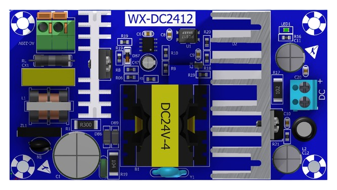
The WX-2412 is a compact, high-performance DC-DC converter designed for efficient voltage regulation in various electronic applications. It is ideal for scenarios requiring stable and adjustable output voltages, such as powering microcontrollers, sensors, and other low-power devices. The WX-2412 is equipped with a wide input voltage range, adjustable output voltage, and built-in protection mechanisms, including overcurrent and thermal shutdown, ensuring reliable operation in demanding environments.

Explore Projects Built with WX-2412

Use Cirkit Designer to design, explore, and prototype these projects online. Some projects support real-time simulation. Click "Open Project" to start designing instantly!
Satellite-Based Timing and Navigation System with SDR and Atomic Clock Synchronization
Image of GPS 시스템 측정 구성도_Confirm: A project utilizing WX-2412 in a practical application
This circuit appears to be a complex system involving power supply management, GPS and timing synchronization, and data communication. It includes a SI-TEX G1 Satellite Compass for GPS data, an XHTF1021 Atomic Rubidium Clock for precise timing, and Ettus USRP B200 units for software-defined radio communication. Power is supplied through various SMPS units and distributed via terminal blocks and DC jacks. Data communication is facilitated by Beelink MINI S12 N95 computers, RS232 splitters, and a 1000BASE-T Media Converter for network connectivity. RF Directional Couplers are used to interface antennas with the USRP units, and the entire system is likely contained within cases for protection and organization.
Cirkit Designer LogoOpen Project in Cirkit Designer
ESP32C3-Based Smart AC Light Controller with Voltage Sensing
Image of plugins: A project utilizing WX-2412 in a practical application
This circuit appears to be a smart AC power control system. The XIAO ESP32C3 microcontroller is used to monitor AC voltage through the ZMPT101B module and to control a 12v Relay, which in turn switches an AC Bulb on or off. The Mini AC-DC module provides the 5V power required by the microcontroller and the relay, while the AC Wire provides the AC power to the system.
Cirkit Designer LogoOpen Project in Cirkit Designer
ESP32-Based Smart Energy Monitoring and Control System
Image of SMART SOCKET: A project utilizing WX-2412 in a practical application
This circuit is designed to monitor AC voltage and current using ZMPT101B and ZMCT103C sensors, respectively, with an ESP32 microcontroller processing the sensor outputs. The XL4015 step-down module regulates the power supply to provide a stable voltage to the sensors, the ESP32, and an LCD I2C display. The ESP32 controls a 4-channel relay module for switching AC loads, and the system's operation can be interacted with via the LCD display and a push switch.
Cirkit Designer LogoOpen Project in Cirkit Designer
ESP32C3 and SIM800L Powered Smart Energy Monitor with OLED Display and Wi-Fi Connectivity
Image of SERVER: A project utilizing WX-2412 in a practical application
This circuit is a power monitoring system that uses an ESP32C3 microcontroller to collect power usage data from slave devices via WiFi and SMS. The collected data is displayed on a 0.96" OLED screen, and the system is powered by an AC-DC converter module. Additionally, the circuit includes a SIM800L GSM module for SMS communication and LEDs for status indication.
Cirkit Designer LogoOpen Project in Cirkit Designer

Explore Projects Built with WX-2412

Use Cirkit Designer to design, explore, and prototype these projects online. Some projects support real-time simulation. Click "Open Project" to start designing instantly!
Image of GPS 시스템 측정 구성도_Confirm: A project utilizing WX-2412 in a practical application
Satellite-Based Timing and Navigation System with SDR and Atomic Clock Synchronization
This circuit appears to be a complex system involving power supply management, GPS and timing synchronization, and data communication. It includes a SI-TEX G1 Satellite Compass for GPS data, an XHTF1021 Atomic Rubidium Clock for precise timing, and Ettus USRP B200 units for software-defined radio communication. Power is supplied through various SMPS units and distributed via terminal blocks and DC jacks. Data communication is facilitated by Beelink MINI S12 N95 computers, RS232 splitters, and a 1000BASE-T Media Converter for network connectivity. RF Directional Couplers are used to interface antennas with the USRP units, and the entire system is likely contained within cases for protection and organization.
Cirkit Designer LogoOpen Project in Cirkit Designer
Image of plugins: A project utilizing WX-2412 in a practical application
ESP32C3-Based Smart AC Light Controller with Voltage Sensing
This circuit appears to be a smart AC power control system. The XIAO ESP32C3 microcontroller is used to monitor AC voltage through the ZMPT101B module and to control a 12v Relay, which in turn switches an AC Bulb on or off. The Mini AC-DC module provides the 5V power required by the microcontroller and the relay, while the AC Wire provides the AC power to the system.
Cirkit Designer LogoOpen Project in Cirkit Designer
Image of SMART SOCKET: A project utilizing WX-2412 in a practical application
ESP32-Based Smart Energy Monitoring and Control System
This circuit is designed to monitor AC voltage and current using ZMPT101B and ZMCT103C sensors, respectively, with an ESP32 microcontroller processing the sensor outputs. The XL4015 step-down module regulates the power supply to provide a stable voltage to the sensors, the ESP32, and an LCD I2C display. The ESP32 controls a 4-channel relay module for switching AC loads, and the system's operation can be interacted with via the LCD display and a push switch.
Cirkit Designer LogoOpen Project in Cirkit Designer
Image of SERVER: A project utilizing WX-2412 in a practical application
ESP32C3 and SIM800L Powered Smart Energy Monitor with OLED Display and Wi-Fi Connectivity
This circuit is a power monitoring system that uses an ESP32C3 microcontroller to collect power usage data from slave devices via WiFi and SMS. The collected data is displayed on a 0.96" OLED screen, and the system is powered by an AC-DC converter module. Additionally, the circuit includes a SIM800L GSM module for SMS communication and LEDs for status indication.
Cirkit Designer LogoOpen Project in Cirkit Designer

Common Applications and Use Cases

  • Powering microcontrollers (e.g., Arduino, Raspberry Pi)
  • Voltage regulation for sensors and modules
  • Battery-powered devices
  • Industrial control systems
  • Portable electronics

Technical Specifications

Key Technical Details

Parameter Value
Input Voltage Range 6V to 24V
Output Voltage Range 1.2V to 12V (adjustable)
Maximum Output Current 2A
Efficiency Up to 92%
Switching Frequency 150 kHz
Protection Features Overcurrent, Thermal Shutdown
Operating Temperature -40°C to +85°C
Package Type Compact DIP-8 or SMD

Pin Configuration and Descriptions

Pin Number Pin Name Description
1 VIN Input voltage (6V to 24V)
2 GND Ground connection
3 VOUT Regulated output voltage (1.2V to 12V)
4 ADJ Output voltage adjustment pin
5 EN Enable pin (active high, logic level control)
6 NC No connection (leave unconnected)
7 PG Power good indicator (open-drain output)
8 SYNC Synchronization input for external clock signal

Usage Instructions

How to Use the WX-2412 in a Circuit

  1. Power Input: Connect the input voltage (6V to 24V) to the VIN pin and ground to the GND pin.
  2. Output Voltage Adjustment: Use a resistor divider or potentiometer connected to the ADJ pin to set the desired output voltage. Refer to the datasheet for the exact formula.
  3. Enable Pin: To enable the converter, apply a logic high signal (e.g., 3.3V or 5V) to the EN pin. Leave it floating or pull it low to disable the converter.
  4. Power Good Indicator: Use the PG pin to monitor the output voltage status. This pin is open-drain and requires a pull-up resistor.
  5. Synchronization: If needed, connect an external clock signal to the SYNC pin to synchronize the switching frequency.

Important Considerations and Best Practices

  • Input Capacitor: Place a low-ESR capacitor (e.g., 10µF) close to the VIN pin to stabilize the input voltage.
  • Output Capacitor: Use a low-ESR capacitor (e.g., 22µF) at the VOUT pin to ensure stable output voltage.
  • Thermal Management: Ensure adequate ventilation or heat sinking if operating near the maximum current or in high-temperature environments.
  • Voltage Adjustment: When adjusting the output voltage, ensure the resistor values are chosen to avoid exceeding the maximum output voltage rating.
  • Enable Pin: If the EN pin is not used, connect it to VIN through a pull-up resistor to keep the converter enabled.

Example: Connecting WX-2412 to an Arduino UNO

Below is an example of how to use the WX-2412 to power an Arduino UNO with a 5V output:

Circuit Connections

  • Connect a 12V DC power supply to the VIN pin.
  • Connect the GND pin to the ground of the power supply and Arduino.
  • Adjust the ADJ pin to set the output voltage to 5V.
  • Connect the VOUT pin to the Arduino's 5V input pin.

Arduino Code Example

// Example code to monitor the Power Good (PG) pin of the WX-2412
// This code assumes the PG pin is connected to Arduino digital pin 2.

const int pgPin = 2; // Power Good pin connected to digital pin 2
const int ledPin = 13; // Onboard LED for status indication

void setup() {
  pinMode(pgPin, INPUT); // Set PG pin as input
  pinMode(ledPin, OUTPUT); // Set LED pin as output
  digitalWrite(ledPin, LOW); // Turn off LED initially
  Serial.begin(9600); // Initialize serial communication
}

void loop() {
  int pgStatus = digitalRead(pgPin); // Read the PG pin status

  if (pgStatus == HIGH) {
    // PG pin is HIGH, output voltage is stable
    digitalWrite(ledPin, HIGH); // Turn on LED
    Serial.println("Output voltage is stable.");
  } else {
    // PG pin is LOW, output voltage is not stable
    digitalWrite(ledPin, LOW); // Turn off LED
    Serial.println("Output voltage is not stable.");
  }

  delay(500); // Wait for 500ms before checking again
}

Troubleshooting and FAQs

Common Issues and Solutions

  1. No Output Voltage

    • Cause: The EN pin is not connected or is pulled low.
    • Solution: Ensure the EN pin is connected to a logic high signal or VIN through a pull-up resistor.
  2. Output Voltage is Unstable

    • Cause: Insufficient input or output capacitance.
    • Solution: Add low-ESR capacitors close to the VIN and VOUT pins.
  3. Overheating

    • Cause: Operating near maximum current without proper cooling.
    • Solution: Improve ventilation or add a heat sink to the component.
  4. PG Pin Always Low

    • Cause: Output voltage is not within the expected range.
    • Solution: Verify the resistor divider values and ensure the input voltage is sufficient.

FAQs

Q: Can the WX-2412 be used with a 24V input to output 1.2V?
A: Yes, the WX-2412 supports a wide input voltage range (6V to 24V) and can regulate down to 1.2V, provided the output current does not exceed 2A.

Q: What happens if the input voltage exceeds 24V?
A: The WX-2412 is not designed to handle input voltages above 24V. Exceeding this limit may damage the component.

Q: Can I leave the SYNC pin unconnected?
A: Yes, the SYNC pin can be left unconnected if external synchronization is not required.