How to Use ESP 8266: Examples, Pinouts, and Specs
Introduction
The ESP 8266, manufactured by ESP, is a low-cost Wi-Fi microchip with a full TCP/IP stack and microcontroller capability. It is widely used in Internet of Things (IoT) applications to enable devices to connect to the internet. The ESP 8266 is highly versatile, offering both standalone operation as a microcontroller and integration with other microcontrollers for Wi-Fi connectivity.
Explore Projects Built with ESP 8266


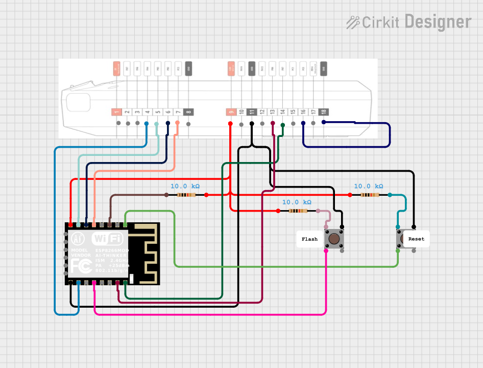
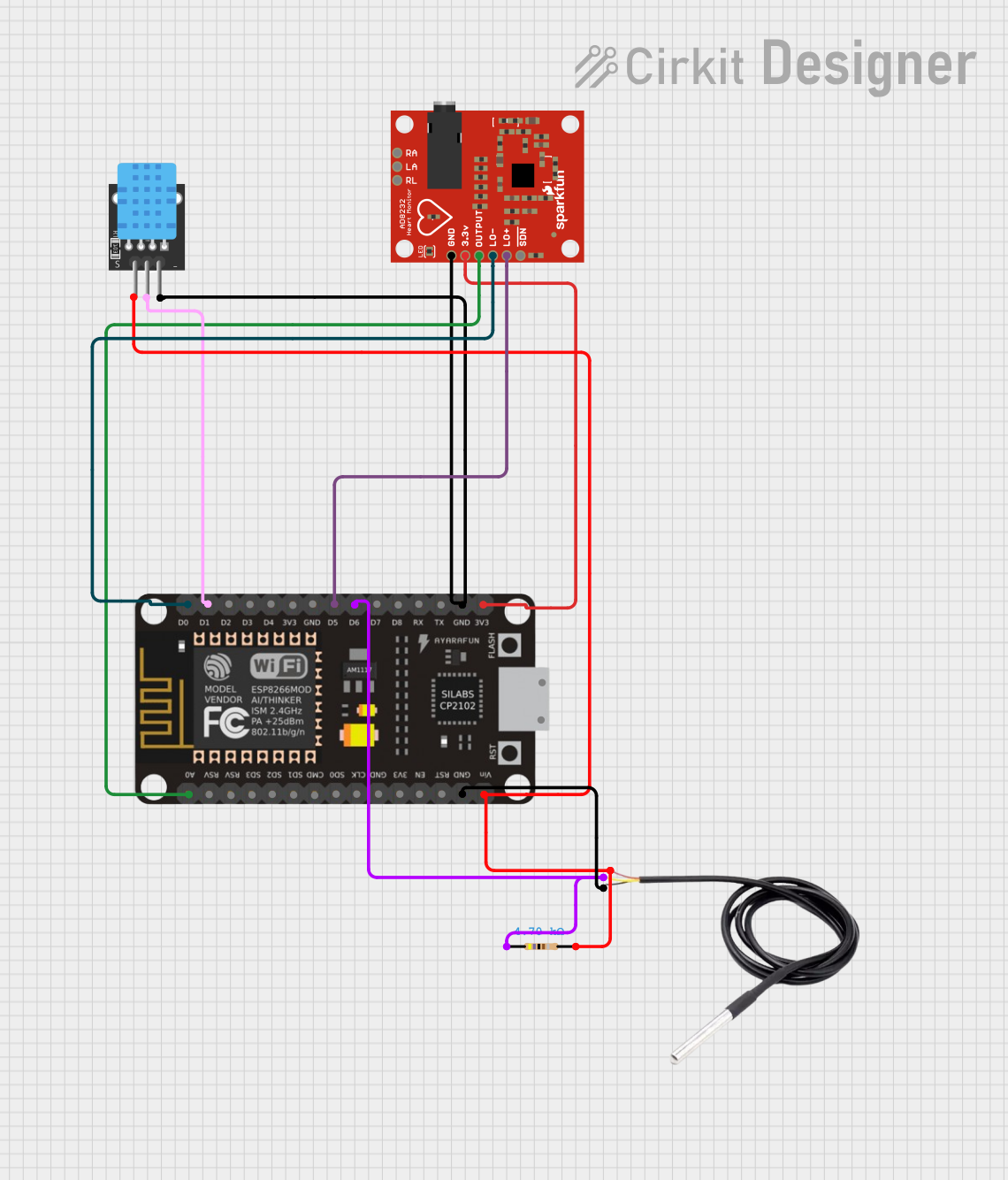
Explore Projects Built with ESP 8266
Common Applications and Use Cases
- Home automation systems
- Smart appliances
- IoT sensor networks
- Wireless data logging
- Remote device control
- Prototyping and development of connected devices
Technical Specifications
The ESP 8266 is a powerful and compact module with the following key specifications:
| Parameter | Value |
|---|---|
| Manufacturer | ESP |
| Part ID | 8266 |
| Operating Voltage | 3.0V - 3.6V |
| Operating Current | 80mA (average), up to 200mA (peak) |
| Wi-Fi Standard | IEEE 802.11 b/g/n |
| Processor | 32-bit Tensilica L106 running at 80 MHz |
| Flash Memory | 512 KB to 4 MB (depending on module type) |
| GPIO Pins | Up to 17 (varies by module) |
| Communication Interfaces | UART, SPI, I2C, PWM, ADC |
| Maximum Wi-Fi Range | ~100 meters (line of sight) |
| Operating Temperature | -40°C to 125°C |
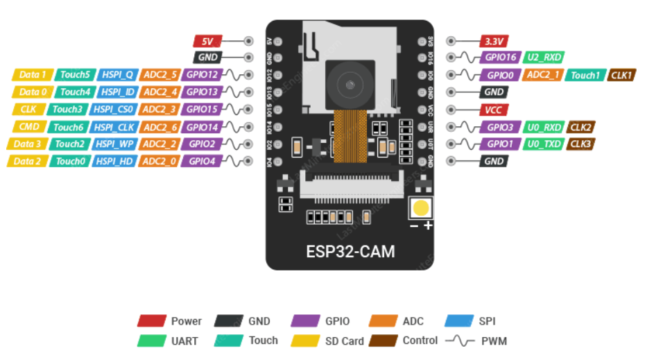
Pin Configuration and Descriptions
The ESP 8266 is available in various module formats, such as ESP-01, ESP-12E, and others. Below is the pin configuration for the popular ESP-12E module:
| Pin Name | Pin Number | Description |
|---|---|---|
| VCC | 1 | Power supply (3.3V) |
| GND | 2 | Ground |
| TX | 3 | UART Transmit (for serial communication) |
| RX | 4 | UART Receive (for serial communication) |
| GPIO0 | 5 | General-purpose I/O pin, used for boot mode |
| GPIO2 | 6 | General-purpose I/O pin |
| GPIO15 | 7 | General-purpose I/O pin, used for boot mode |
| EN (CH_PD) | 8 | Chip enable (active high, must be connected to VCC) |
| RST | 9 | Reset pin (active low) |
| ADC (A0) | 10 | Analog-to-digital converter input |
Usage Instructions
The ESP 8266 can be used as a standalone microcontroller or as a Wi-Fi module for other microcontrollers like the Arduino UNO. Below are the steps to use the ESP 8266 in a circuit:
Connecting the ESP 8266 to an Arduino UNO
- Power Supply: Connect the VCC pin of the ESP 8266 to a 3.3V power source. Do not connect it to 5V, as this may damage the module.
- Ground: Connect the GND pin to the ground of the power supply and the Arduino.
- UART Communication: Connect the TX pin of the ESP 8266 to the RX pin of the Arduino, and the RX pin of the ESP 8266 to the TX pin of the Arduino. Use a voltage divider or level shifter to step down the Arduino's 5V TX signal to 3.3V.
- Enable Pin: Connect the EN (CH_PD) pin to 3.3V to enable the module.
- Boot Mode: Ensure GPIO0 is connected to 3.3V for normal operation. For flashing firmware, connect GPIO0 to GND.
Example Code for Arduino UNO
The following example demonstrates how to send AT commands to the ESP 8266 to connect to a Wi-Fi network:
#include <SoftwareSerial.h>

// Create a software serial object to communicate with ESP 8266
SoftwareSerial espSerial(2, 3); // RX, TX

void setup() {
  // Initialize serial communication with the ESP 8266
  espSerial.begin(9600);
  // Initialize serial communication with the computer
  Serial.begin(9600);

  // Wait for the ESP 8266 to initialize
  delay(2000);

  // Send AT command to test communication
  espSerial.println("AT");
  delay(1000);

  // Connect to Wi-Fi network
  espSerial.println("AT+CWJAP=\"YourSSID\",\"YourPassword\"");
  delay(5000);

  // Print response from ESP 8266
  while (espSerial.available()) {
    Serial.write(espSerial.read());
  }
}

void loop() {
  // Continuously read data from ESP 8266 and print to Serial Monitor
  if (espSerial.available()) {
    Serial.write(espSerial.read());
  }
}
Important Considerations and Best Practices
- Always use a 3.3V power supply for the ESP 8266. If using a 5V source, use a voltage regulator.
- Use a level shifter or voltage divider for UART communication to avoid damaging the module.
- Ensure proper decoupling capacitors are used near the power pins to stabilize the power supply.
- Avoid exposing the module to high temperatures or humidity.
Troubleshooting and FAQs
Common Issues
ESP 8266 Not Responding to AT Commands
- Ensure the baud rate matches the module's default (usually 9600 or 115200).
- Verify the wiring, especially the TX and RX connections.
- Check that the EN (CH_PD) pin is connected to 3.3V.
Wi-Fi Connection Fails
- Double-check the SSID and password in the AT+CWJAP command.
- Ensure the Wi-Fi network is within range and not using unsupported security protocols.
Module Overheating
- Verify that the power supply is stable and within the 3.0V-3.6V range.
- Check for short circuits or excessive current draw.
Tips for Troubleshooting
- Use a USB-to-serial adapter to directly communicate with the ESP 8266 for debugging.
- Monitor the module's response to AT commands to identify issues.
- If the module is unresponsive, try resetting it by pulling the RST pin low momentarily.
By following this documentation, users can effectively integrate the ESP 8266 into their projects and troubleshoot common issues.