How to Use IR LED: Examples, Pinouts, and Specs
Introduction
An Infrared Light Emitting Diode (IR LED) emits infrared light, which is invisible to the human eye but detectable by electronic sensors. When an electric current passes through the diode, it produces infrared radiation. IR LEDs are widely used in applications such as remote controls, proximity sensors, optical communication systems, and security systems. Their ability to transmit data wirelessly and detect objects makes them a versatile component in modern electronics.
Explore Projects Built with IR LED
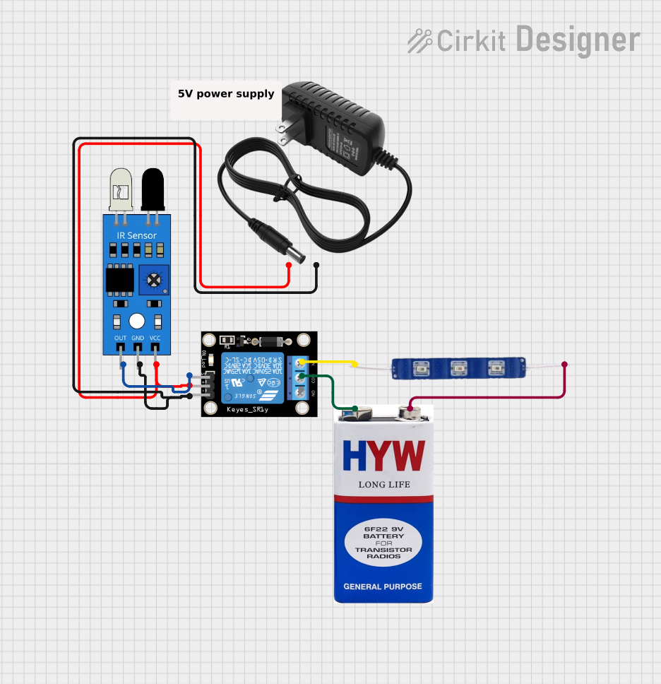
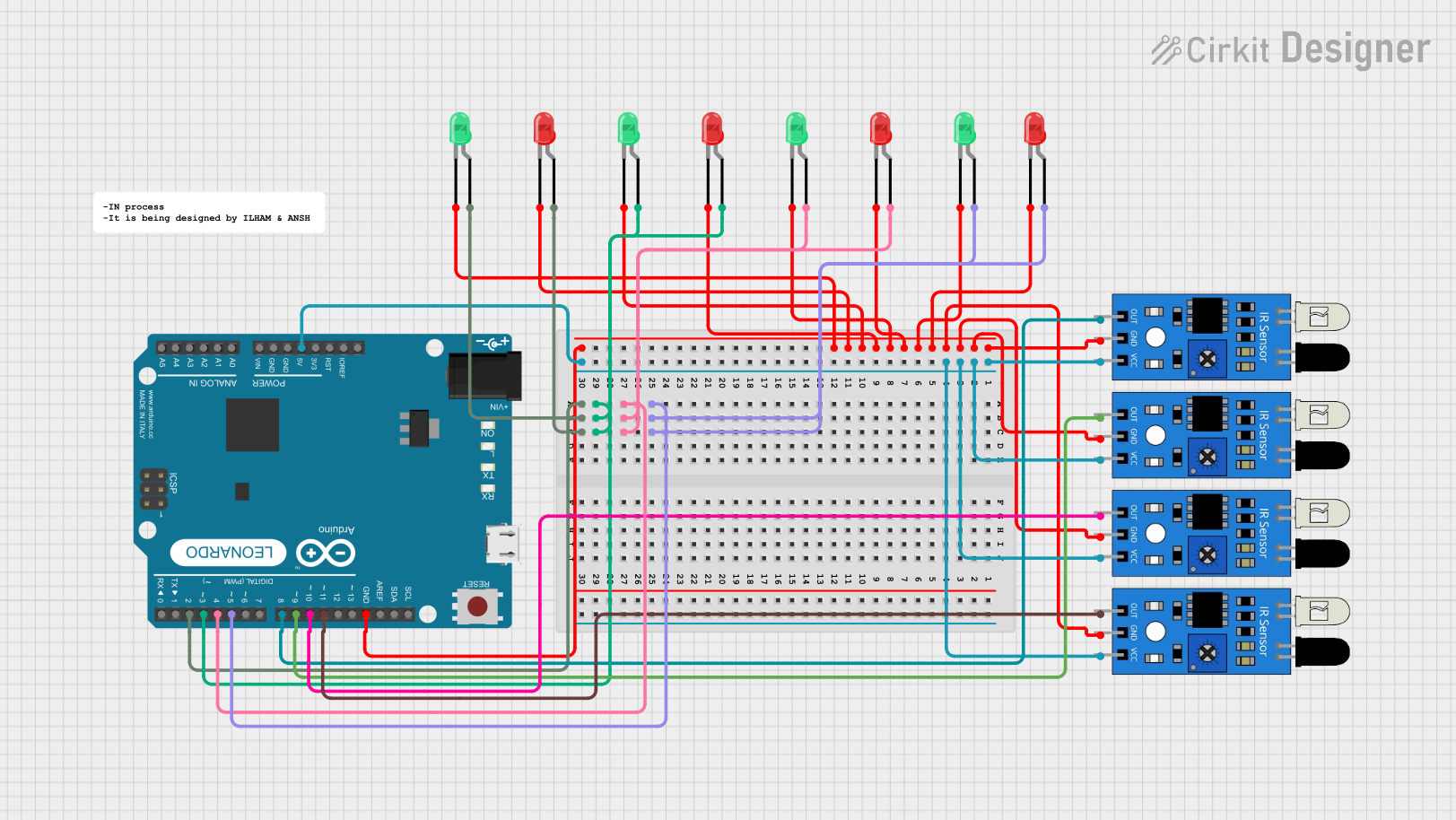
Explore Projects Built with IR LED
Technical Specifications
Below are the key technical details and pin configuration for a typical IR LED:
Key Technical Details
- Wavelength: 850 nm to 950 nm (typical range for IR LEDs)
- Forward Voltage (Vf): 1.2V to 1.5V
- Forward Current (If): 20 mA (typical), maximum 50 mA
- Power Dissipation: 100 mW (maximum)
- Viewing Angle: 20° to 60° (varies by model)
- Operating Temperature: -40°C to +85°C
Pin Configuration
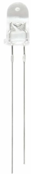
An IR LED typically has two pins: the anode (positive) and the cathode (negative). The table below describes the pin configuration:
| Pin | Description | Identification |
|---|---|---|
| Anode | Positive terminal; connects to Vcc | Longer leg of the LED |
| Cathode | Negative terminal; connects to ground | Shorter leg of the LED or flat edge |
Usage Instructions
How to Use the IR LED in a Circuit
Connect the IR LED:
- Connect the anode (longer leg) to the positive terminal of the power supply through a current-limiting resistor.
- Connect the cathode (shorter leg) to the ground.
Choose a Resistor:
- Use Ohm's Law to calculate the resistor value:
( R = \frac{V_{supply} - V_f}{I_f} )
For example, if the supply voltage is 5V, the forward voltage is 1.2V, and the desired current is 20 mA:
( R = \frac{5V - 1.2V}{0.02A} = 190 , \Omega ).
Use a 220 Ω resistor (standard value) for safety.
- Use Ohm's Law to calculate the resistor value:
Test the IR LED:
- Use a digital camera or smartphone camera to verify the IR LED is emitting light. The camera can detect infrared light as a faint purple glow.
Integrate with Sensors:
- Pair the IR LED with an IR receiver module for applications like remote control or object detection.
Important Considerations and Best Practices
- Always use a current-limiting resistor to prevent damage to the IR LED.
- Avoid exceeding the maximum forward current (50 mA) to ensure longevity.
- Ensure proper alignment with the IR receiver for optimal performance in communication or sensing applications.
- Use a heat sink or proper ventilation if the IR LED is used continuously at high currents.
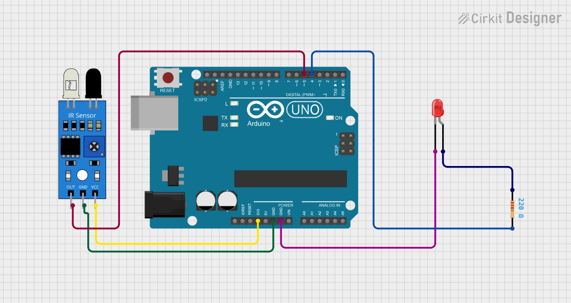
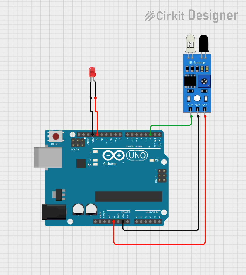
Example: Using an IR LED with Arduino UNO
Below is an example of how to use an IR LED with an Arduino UNO to blink the LED at regular intervals:
// Define the pin connected to the IR LED
const int irLedPin = 9;

void setup() {
  // Set the IR LED pin as an output
  pinMode(irLedPin, OUTPUT);
}

void loop() {
  // Turn the IR LED on
  digitalWrite(irLedPin, HIGH);
  delay(500); // Wait for 500 milliseconds

  // Turn the IR LED off
  digitalWrite(irLedPin, LOW);
  delay(500); // Wait for 500 milliseconds
}
Note: Use a 220 Ω resistor in series with the IR LED to limit the current.
Troubleshooting and FAQs
Common Issues and Solutions
IR LED Not Emitting Light:
- Cause: Incorrect polarity or no current-limiting resistor.
- Solution: Ensure the anode is connected to the positive terminal and the cathode to ground. Use a resistor to limit current.
IR LED Overheating:
- Cause: Excessive current through the LED.
- Solution: Verify the resistor value and ensure it limits the current to 20 mA.
IR LED Not Detected by Receiver:
- Cause: Misalignment or interference.
- Solution: Align the IR LED and receiver properly. Check for obstacles or ambient IR interference.
IR LED Not Visible to Camera:
- Cause: Faulty LED or low current.
- Solution: Test the LED with a multimeter. Increase the current slightly (within safe limits).
FAQs
Q: Can I use an IR LED without a resistor?
A: No, a resistor is essential to prevent excessive current, which can damage the LED.Q: How far can an IR LED transmit?
A: The range depends on the power of the LED and the sensitivity of the receiver. Typical ranges are 5–10 meters.Q: Can I use an IR LED for data communication?
A: Yes, IR LEDs are commonly used in remote controls and optical communication systems.Q: How do I know if my IR LED is working?
A: Use a digital camera or smartphone camera to check for a faint purple glow when the LED is powered.
By following this documentation, you can effectively use an IR LED in your projects and troubleshoot common issues.