How to Use XL4005 - Adjustable Step Down Power Supply Module: Examples, Pinouts, and Specs
Introduction
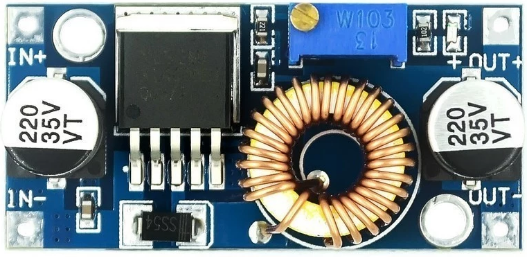
The XL4005 is a DC-DC buck converter module designed to efficiently step down a higher input voltage to a lower, adjustable output voltage. It features a built-in potentiometer for easy voltage adjustment and supports a wide range of input and output voltages, making it versatile for various applications. The module is highly efficient, compact, and capable of delivering high output current, making it suitable for powering devices that require a specific voltage level.
Explore Projects Built with XL4005 - Adjustable Step Down Power Supply Module


Explore Projects Built with XL4005 - Adjustable Step Down Power Supply Module
Common Applications and Use Cases
- Powering microcontrollers, sensors, and other low-voltage devices
- Battery charging circuits
- LED drivers
- DIY electronics projects
- Voltage regulation in automotive or industrial systems
Technical Specifications
Below are the key technical details of the XL4005 module:
| Parameter | Value |
|---|---|
| Input Voltage Range | 5V to 32V |
| Output Voltage Range | 0.8V to 30V (adjustable via potentiometer) |
| Maximum Output Current | 5A (with proper heat dissipation) |
| Output Power | Up to 75W |
| Efficiency | Up to 96% (depending on input/output ratio) |
| Switching Frequency | 300 kHz |
| Operating Temperature | -40°C to +85°C |
| Dimensions | 51mm x 26mm x 14mm |
Pin Configuration and Descriptions
The XL4005 module has the following input and output connections:
| Pin | Label | Description |
|---|---|---|
| 1 | VIN+ | Positive input voltage (5V to 32V) |
| 2 | VIN- | Negative input voltage (GND) |
| 3 | VOUT+ | Positive output voltage (adjustable) |
| 4 | VOUT- | Negative output voltage (GND) |
Usage Instructions
How to Use the XL4005 in a Circuit
Connect the Input Voltage:
- Connect the positive terminal of your power source to the
VIN+pin. - Connect the negative terminal of your power source to the
VIN-pin.
- Connect the positive terminal of your power source to the
Connect the Output Load:
- Connect the positive terminal of your load to the
VOUT+pin. - Connect the negative terminal of your load to the
VOUT-pin.
- Connect the positive terminal of your load to the
Adjust the Output Voltage:
- Use the onboard potentiometer to adjust the output voltage.
- Turn the potentiometer clockwise to increase the voltage and counterclockwise to decrease it.
- Use a multimeter to measure the output voltage for precise adjustment.
Ensure Proper Heat Dissipation:
- If the module is operating at high currents (above 3A), attach a heatsink to the XL4005 IC to prevent overheating.
Important Considerations and Best Practices
- Input Voltage: Ensure the input voltage is at least 1.5V higher than the desired output voltage for proper operation.
- Current Limitation: Do not exceed the maximum output current of 5A. Use proper heat dissipation methods if operating near the maximum current.
- Polarity: Double-check the polarity of the input and output connections to avoid damaging the module.
- Load Testing: Before connecting sensitive devices, test the output voltage and current with a dummy load to ensure proper operation.
Example: Using XL4005 with Arduino UNO
The XL4005 can be used to power an Arduino UNO by stepping down a higher voltage (e.g., 12V) to 5V. Below is an example circuit and Arduino code to demonstrate its use:
Circuit Setup
- Connect a 12V power source to the
VIN+andVIN-pins of the XL4005. - Adjust the output voltage to 5V using the potentiometer.
- Connect the
VOUT+pin to the Arduino UNO's 5V pin. - Connect the
VOUT-pin to the Arduino UNO's GND pin.
Arduino Code Example
// Example code to blink an LED connected to pin 13 of the Arduino UNO
// Ensure the XL4005 is providing a stable 5V to the Arduino UNO

void setup() {
  pinMode(13, OUTPUT); // Set pin 13 as an output
}

void loop() {
  digitalWrite(13, HIGH); // Turn the LED on
  delay(1000);            // Wait for 1 second
  digitalWrite(13, LOW);  // Turn the LED off
  delay(1000);            // Wait for 1 second
}
Troubleshooting and FAQs
Common Issues and Solutions
No Output Voltage:
- Cause: Incorrect input connections or insufficient input voltage.
- Solution: Verify the polarity and ensure the input voltage is within the specified range.
Output Voltage Not Adjustable:
- Cause: Faulty potentiometer or incorrect adjustment.
- Solution: Check the potentiometer for damage and ensure you are turning it in the correct direction.
Overheating:
- Cause: High output current or insufficient heat dissipation.
- Solution: Attach a heatsink to the XL4005 IC and ensure proper ventilation.
Load Not Powering On:
- Cause: Output voltage too low or load requires more current than the module can provide.
- Solution: Adjust the output voltage to the required level and ensure the load's current demand is within the module's limits.
FAQs
Q: Can the XL4005 be used to charge batteries?
A: Yes, but you must carefully adjust the output voltage and current to match the battery's charging requirements.Q: What happens if the input voltage exceeds 32V?
A: The module may be damaged. Always ensure the input voltage stays within the specified range.Q: Can I use the XL4005 to power a Raspberry Pi?
A: Yes, but ensure the output voltage is set to 5V and the module can supply sufficient current (at least 2.5A for most Raspberry Pi models).Q: Is the XL4005 isolated?
A: No, the XL4005 is not an isolated power supply module. The input and output grounds are connected.
By following this documentation, you can effectively use the XL4005 module in your projects while avoiding common pitfalls.