How to Use speed sensor: Examples, Pinouts, and Specs
Introduction
A speed sensor is an electronic device designed to measure the speed of an object, typically in terms of rotational or linear velocity. These sensors are widely used in automotive systems to monitor wheel speed, engine RPM, and vehicle speed. They are also employed in industrial applications to track the movement of conveyor belts, motors, and other machinery.
Common applications include:
- Automotive systems (e.g., ABS, cruise control, and speedometers)
- Industrial machinery monitoring
- Robotics and automation
- Fitness equipment (e.g., treadmills)
- Wind speed measurement in weather stations
Explore Projects Built with speed sensor
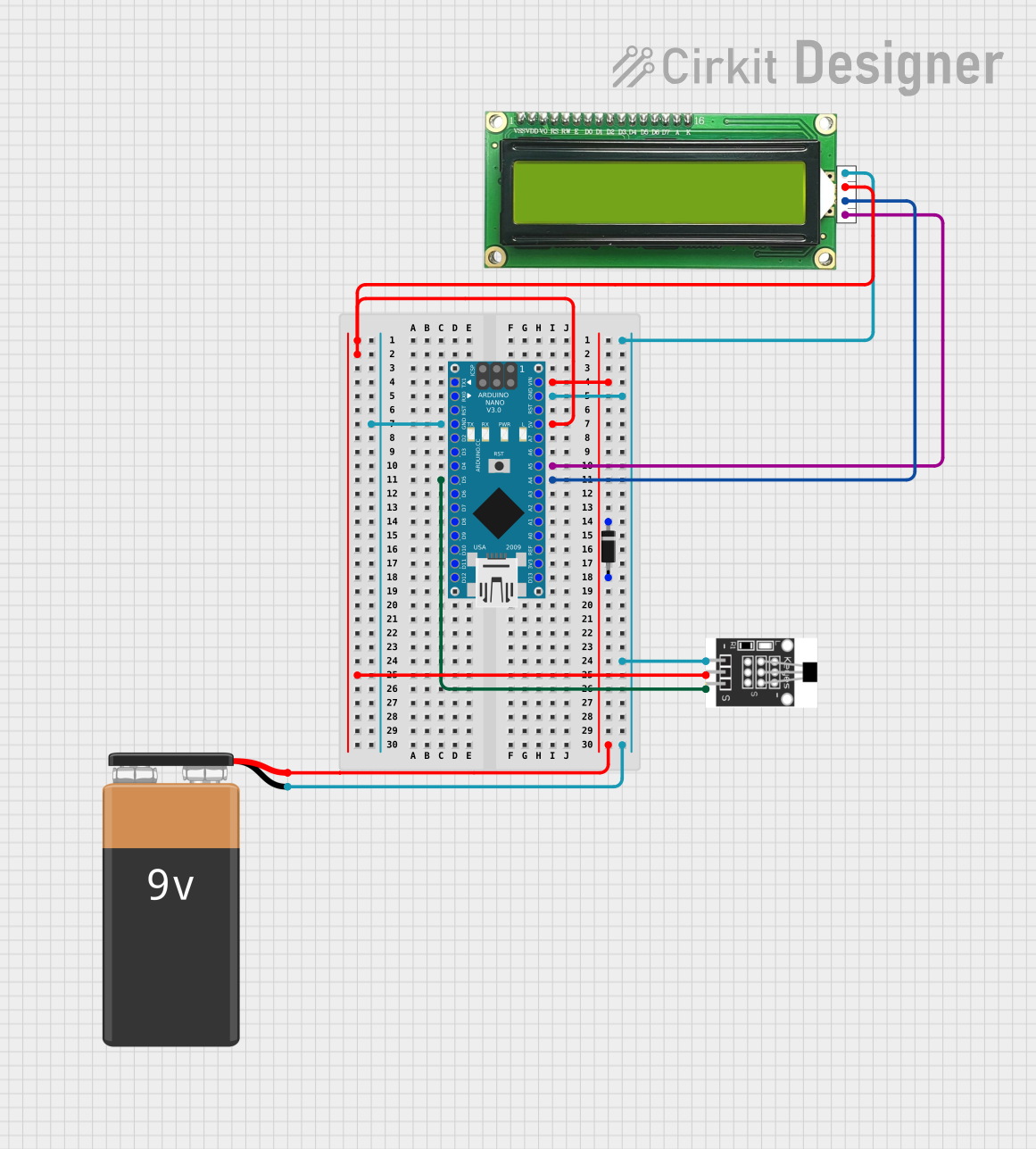
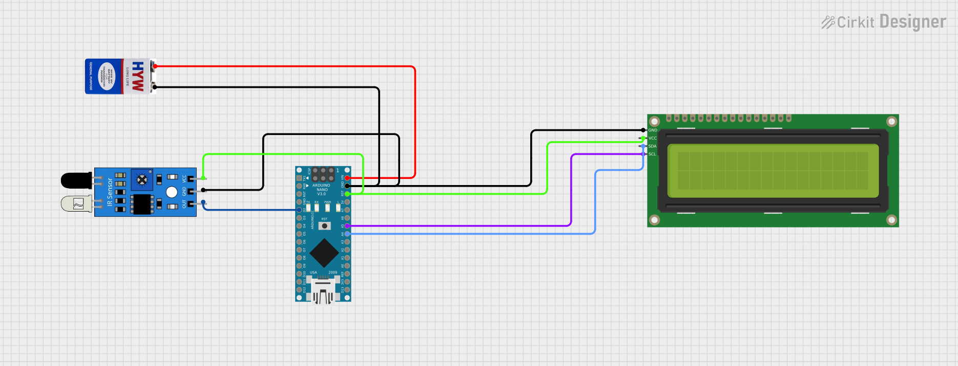
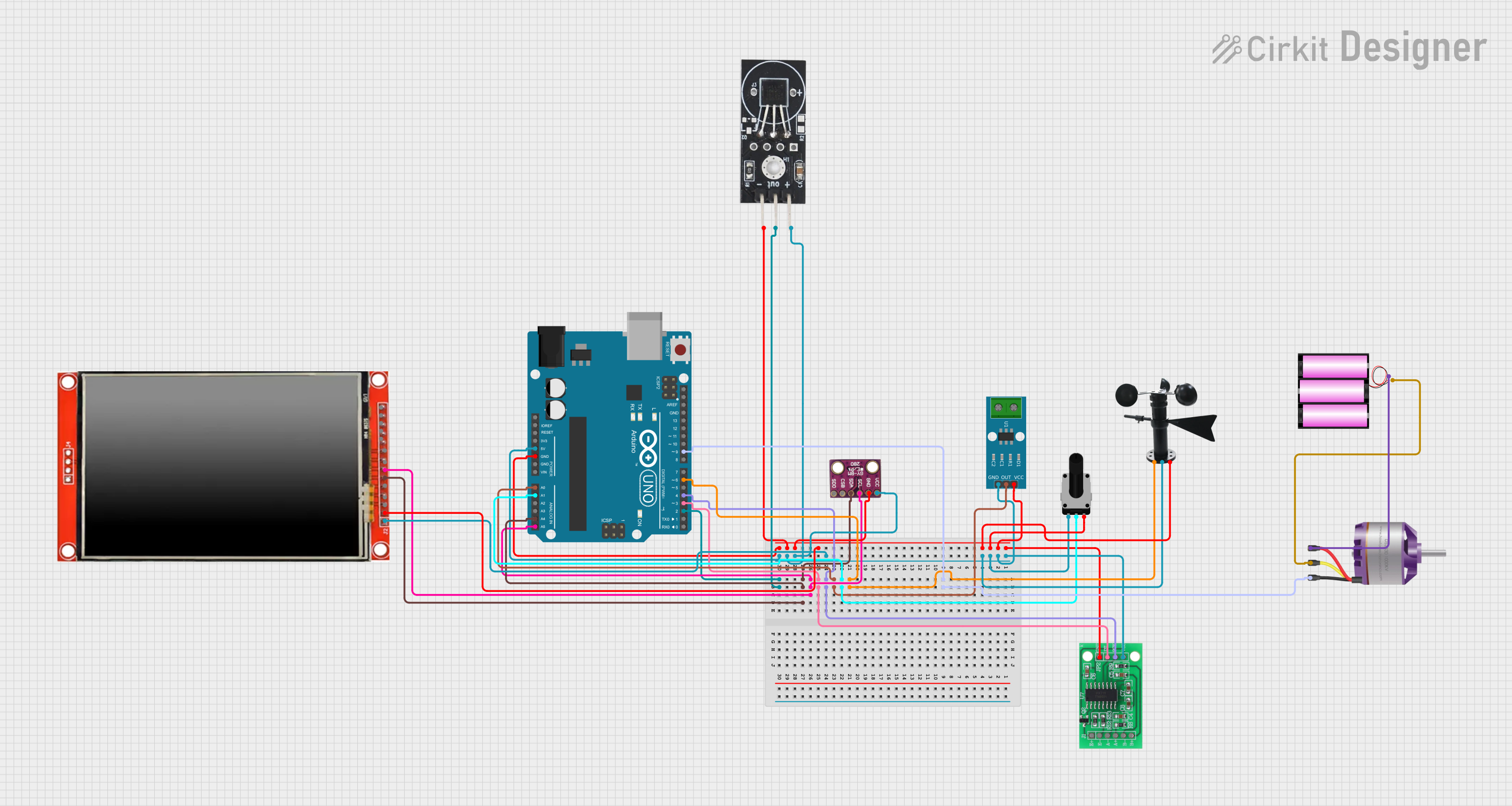
Explore Projects Built with speed sensor
Technical Specifications
The technical specifications of a speed sensor can vary depending on the type and application. Below are general specifications for a typical Hall-effect-based speed sensor:
| Parameter | Value |
|---|---|
| Operating Voltage | 5V to 24V DC |
| Output Signal | Digital (Square Wave) |
| Frequency Range | 0 Hz to 10 kHz |
| Operating Temperature | -40°C to +125°C |
| Sensing Distance | 1 mm to 5 mm (depending on target) |
| Output Current | 10 mA to 20 mA |
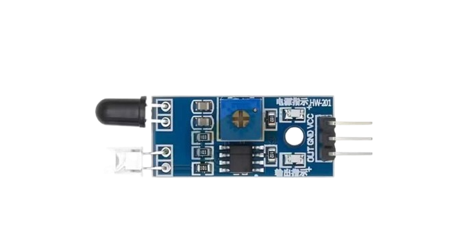
Pin Configuration
The pinout for a 3-pin Hall-effect speed sensor is as follows:
| Pin | Name | Description |
|---|---|---|
| 1 | VCC | Power supply input (5V to 24V DC) |
| 2 | GND | Ground connection |
| 3 | Signal Out | Digital output signal (square wave proportional to speed) |
Usage Instructions
How to Use the Speed Sensor in a Circuit
- Power the Sensor: Connect the VCC pin to a DC power supply (5V to 24V) and the GND pin to the ground of the circuit.
- Connect the Output: Attach the Signal Out pin to a microcontroller or other processing unit to read the speed data.
- Place the Sensor: Position the sensor close to the moving target (e.g., a rotating gear or magnet). Ensure the sensing distance is within the specified range (1 mm to 5 mm).
- Read the Signal: The sensor outputs a square wave signal, where the frequency corresponds to the speed of the target. Use a microcontroller or frequency counter to process the signal.
Important Considerations and Best Practices
- Alignment: Ensure proper alignment between the sensor and the moving target for accurate readings.
- Magnetic Targets: For Hall-effect sensors, use ferromagnetic materials or magnets as the target.
- Debouncing: If the output signal is noisy, consider adding a capacitor or software debouncing to stabilize the readings.
- Power Supply: Use a stable power supply to avoid fluctuations in the output signal.
- Environmental Factors: Protect the sensor from extreme temperatures, moisture, and debris to ensure long-term reliability.
Example Code for Arduino UNO
Below is an example of how to interface a speed sensor with an Arduino UNO to measure rotational speed:
// Define the pin connected to the speed sensor's Signal Out
const int sensorPin = 2;

// Variables to store pulse count and RPM
volatile unsigned int pulseCount = 0;
unsigned long lastTime = 0;
float rpm = 0;

// Interrupt service routine to count pulses
void countPulses() {
  pulseCount++;
}

void setup() {
  pinMode(sensorPin, INPUT_PULLUP); // Set sensor pin as input with pull-up
  attachInterrupt(digitalPinToInterrupt(sensorPin), countPulses, RISING);
  Serial.begin(9600); // Initialize serial communication
}

void loop() {
  unsigned long currentTime = millis();

  // Calculate RPM every second
  if (currentTime - lastTime >= 1000) {
    noInterrupts(); // Disable interrupts to safely access pulseCount
    rpm = (pulseCount / 20.0) * 60.0; // Assuming 20 pulses per revolution
    pulseCount = 0; // Reset pulse count
    interrupts(); // Re-enable interrupts

    Serial.print("RPM: ");
    Serial.println(rpm); // Print RPM to the serial monitor
    lastTime = currentTime;
  }
}
Notes:
- Replace
20.0in the RPM calculation with the actual number of pulses per revolution for your specific setup. - Ensure the sensor is properly aligned with the rotating target for accurate readings.
Troubleshooting and FAQs
Common Issues and Solutions
No Output Signal
- Cause: Incorrect wiring or insufficient power supply.
- Solution: Double-check the connections and ensure the power supply voltage matches the sensor's requirements.
Inconsistent Readings
- Cause: Misalignment between the sensor and the target or excessive noise.
- Solution: Adjust the sensor's position and add a capacitor (e.g., 0.1 µF) across the power supply pins to filter noise.
Low Sensitivity
- Cause: Target material is not suitable or the sensing distance is too large.
- Solution: Use a ferromagnetic target or reduce the distance between the sensor and the target.
Signal Drops at High Speeds
- Cause: Microcontroller or processing unit cannot handle high-frequency signals.
- Solution: Use a faster microcontroller or implement hardware-based frequency counting.
FAQs
Q1: Can I use the speed sensor with a 3.3V microcontroller?
A1: Yes, but ensure the sensor's output signal is compatible with the microcontroller's input voltage levels. You may need a voltage divider or level shifter.
Q2: What type of target works best with a Hall-effect speed sensor?
A2: Ferromagnetic materials (e.g., steel) or magnets are ideal targets for Hall-effect sensors.
Q3: How do I calculate speed from the sensor's output?
A3: Measure the frequency of the output signal (in Hz) and use the formula:
Speed = (Frequency × Circumference) / Pulses per Revolution
For rotational speed, this can be converted to RPM as shown in the Arduino example.
Q4: Can the sensor detect linear motion?
A4: Yes, if the linear motion involves a repetitive pattern (e.g., teeth on a gear or slots on a conveyor belt).
By following this documentation, you can effectively integrate and troubleshoot a speed sensor in your projects.