How to Use ESP32-C3 Supermini: Examples, Pinouts, and Specs
Introduction
The ESP32-C3 Supermini is a compact, low-power microcontroller designed for Internet of Things (IoT) applications. It features integrated Wi-Fi and Bluetooth Low Energy (BLE) capabilities, making it ideal for wireless communication in smart devices. Built on a RISC-V architecture, the ESP32-C3 Supermini offers efficient processing, enhanced security features, and a small form factor, making it suitable for space-constrained designs.
Explore Projects Built with ESP32-C3 Supermini


Explore Projects Built with ESP32-C3 Supermini
Common Applications and Use Cases
- Smart home devices (e.g., smart plugs, thermostats, and lighting systems)
- Wearable technology
- Industrial IoT sensors and controllers
- Wireless data logging and monitoring
- Low-power, battery-operated devices
- Prototyping and development of IoT solutions
Technical Specifications
The ESP32-C3 Supermini is packed with features that make it versatile and powerful for a wide range of applications. Below are its key technical specifications:
| Specification | Details |
|---|---|
| Microcontroller Core | RISC-V single-core processor, up to 160 MHz |
| Flash Memory | 4 MB (varies by model) |
| RAM | 400 KB SRAM |
| Wi-Fi | IEEE 802.11 b/g/n (2.4 GHz) |
| Bluetooth | Bluetooth 5.0 Low Energy (BLE) |
| GPIO Pins | 15 GPIO pins (multiplexed with other functions) |
| Operating Voltage | 3.3V |
| Input Voltage Range | 5V (via USB) or 3.3V (via external power supply) |
| Power Consumption | Ultra-low power consumption in deep sleep mode (as low as 5 µA) |
| Interfaces | SPI, I2C, UART, PWM, ADC (12-bit), DAC |
| Security Features | Secure boot, flash encryption, and hardware cryptographic accelerators |
| Dimensions | Approximately 18 mm x 25 mm |
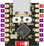
Pin Configuration and Descriptions
The ESP32-C3 Supermini has a compact pinout. Below is a table describing the key pins:
| Pin Name | Type | Description |
|---|---|---|
| 3V3 | Power | 3.3V power supply input/output |
| GND | Power | Ground connection |
| GPIO0 | GPIO/Boot | General-purpose I/O pin; also used for boot mode selection |
| GPIO1 | GPIO/UART TX | General-purpose I/O pin; UART transmit (TX) |
| GPIO2 | GPIO/UART RX | General-purpose I/O pin; UART receive (RX) |
| GPIO3 | GPIO | General-purpose I/O pin |
| GPIO4 | GPIO/I2C SDA | General-purpose I/O pin; I2C data line |
| GPIO5 | GPIO/I2C SCL | General-purpose I/O pin; I2C clock line |
| GPIO6-11 | GPIO/SPI | General-purpose I/O pins; can be used for SPI communication |
| ADC1 | Analog Input | 12-bit ADC input |
| EN | Enable | Chip enable pin; active high |
| RST | Reset | Reset pin; active low |
| USB D+ | USB Data | USB data positive line |
| USB D- | USB Data | USB data negative line |
Usage Instructions
How to Use the ESP32-C3 Supermini in a Circuit
Powering the Module:
- Use a 5V USB power source or provide a regulated 3.3V to the 3V3 pin.
- Ensure proper grounding by connecting the GND pin to the circuit ground.
Programming the Module:
- The ESP32-C3 Supermini can be programmed using the Arduino IDE or the ESP-IDF (Espressif IoT Development Framework).
- Connect the module to your computer via USB. Select the appropriate board and port in the IDE.
Connecting Peripherals:
- Use GPIO pins for digital input/output.
- For analog input, connect sensors to the ADC1 pin.
- Use I2C (GPIO4 and GPIO5) or SPI (GPIO6-11) for communication with external devices.
Flashing Code:
- Hold the GPIO0 pin low while resetting the module to enter bootloader mode.
- Upload your code using the IDE.
Important Considerations and Best Practices
- Voltage Levels: Ensure all connected peripherals operate at 3.3V logic levels to avoid damaging the module.
- Deep Sleep Mode: Use deep sleep mode to minimize power consumption in battery-powered applications.
- Antenna Placement: Avoid placing metal objects near the onboard antenna to ensure optimal Wi-Fi and Bluetooth performance.
- Pull-up Resistors: Use pull-up resistors on I2C lines (SDA and SCL) if not already included in your circuit.
Example Code for Arduino UNO Integration
Below is an example of how to use the ESP32-C3 Supermini to read a temperature sensor and send the data over Wi-Fi:
#include <WiFi.h> // Include the Wi-Fi library

// Wi-Fi credentials
const char* ssid = "Your_SSID";       // Replace with your Wi-Fi SSID
const char* password = "Your_Password"; // Replace with your Wi-Fi password

void setup() {
  Serial.begin(115200); // Initialize serial communication
  WiFi.begin(ssid, password); // Connect to Wi-Fi

  // Wait for connection
  while (WiFi.status() != WL_CONNECTED) {
    delay(1000);
    Serial.println("Connecting to Wi-Fi...");
  }
  Serial.println("Connected to Wi-Fi!");
}

void loop() {
  // Example: Read a sensor value (replace with actual sensor code)
  int sensorValue = analogRead(ADC1); // Read from ADC1 pin
  Serial.print("Sensor Value: ");
  Serial.println(sensorValue);

  delay(1000); // Wait 1 second before the next reading
}
Troubleshooting and FAQs
Common Issues and Solutions
Module Not Detected by Computer:
- Ensure the USB cable is functional and supports data transfer.
- Check if the correct drivers for the ESP32-C3 are installed on your computer.
Wi-Fi Connection Fails:
- Verify the SSID and password are correct.
- Ensure the Wi-Fi network operates on the 2.4 GHz band (not 5 GHz).
Code Upload Fails:
- Ensure the module is in bootloader mode by holding GPIO0 low during reset.
- Check the selected board and port in the Arduino IDE.
Unstable Operation:
- Verify the power supply provides sufficient current (at least 500 mA).
- Avoid noisy power sources that may cause instability.
FAQs
Can the ESP32-C3 Supermini operate on battery power?
Yes, it is designed for low-power operation and can run on batteries. Use deep sleep mode to extend battery life.What is the maximum range of Wi-Fi and Bluetooth?
The range depends on environmental factors, but typically Wi-Fi can reach up to 50 meters indoors, and Bluetooth can reach up to 10 meters.Can I use the ESP32-C3 Supermini with other development boards?
Yes, it can communicate with other boards like Arduino via UART, I2C, or SPI.
This concludes the documentation for the ESP32-C3 Supermini.