How to Use Tacuna Load Cell Signal Conditioner & Amplifier: Examples, Pinouts, and Specs
Introduction
The Tacuna Load Cell Signal Conditioner & Amplifier (Part ID: EMBSGB200) is a precision device designed to amplify and condition the low-level signals generated by load cells. Load cells typically produce weak millivolt-level signals that are susceptible to noise and interference. The EMBSGB200 ensures accurate measurement of weight or force by amplifying these signals, filtering out noise, and providing a stable, high-level output suitable for further processing by microcontrollers, data acquisition systems, or other electronic devices.
Explore Projects Built with Tacuna Load Cell Signal Conditioner & Amplifier


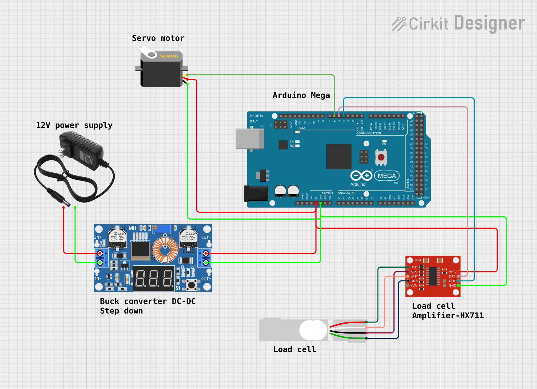
Explore Projects Built with Tacuna Load Cell Signal Conditioner & Amplifier
Common Applications and Use Cases
- Weighing Systems: Used in industrial scales, laboratory balances, and retail weighing machines.
- Force Measurement: Ideal for applications requiring precise force measurement, such as material testing or robotics.
- Automation Systems: Integrated into automated systems for monitoring and controlling weight or force.
- Data Acquisition: Converts load cell signals into a format suitable for data logging or analysis.
Technical Specifications
The following table outlines the key technical details of the EMBSGB200:
| Parameter | Specification |
|---|---|
| Input Signal Range | ±3.3 mV/V |
| Output Signal Range | 0–5 V (single-ended) or ±5 V (differential) |
| Supply Voltage | 5–12 V DC |
| Input Impedance | ≥1 MΩ |
| Output Impedance | ≤1 kΩ |
| Gain Adjustment Range | 0–1000 (adjustable via potentiometer) |
| Operating Temperature Range | -10°C to 50°C |
| Dimensions | 50 mm x 25 mm x 10 mm |
Pin Configuration and Descriptions
The EMBSGB200 features a simple pinout for easy integration into circuits. The table below describes each pin:
| Pin Name | Type | Description |
|---|---|---|
| VCC | Power Input | Connect to a 5–12 V DC power supply. |
| GND | Power Ground | Ground connection for the power supply. |
| IN+ | Signal Input | Positive input from the load cell (excitation signal). |
| IN- | Signal Input | Negative input from the load cell (excitation signal). |
| OUT+ | Signal Output | Positive amplified output signal (single-ended or differential, depending on use). |
| OUT- | Signal Output | Negative amplified output signal (used in differential mode). |
Usage Instructions
How to Use the Component in a Circuit
- Power the Amplifier: Connect the VCC pin to a 5–12 V DC power supply and the GND pin to the ground of the same power source.
- Connect the Load Cell: Attach the load cell's positive and negative excitation signals to the IN+ and IN- pins, respectively.
- Adjust the Gain: Use the onboard potentiometer to adjust the gain of the amplifier. Start with a low gain setting and gradually increase it until the desired output range is achieved.
- Read the Output: Connect the OUT+ pin to the input of your microcontroller, ADC (Analog-to-Digital Converter), or data acquisition system. If using differential mode, also connect the OUT- pin.
Important Considerations and Best Practices
- Shielded Cables: Use shielded cables for the load cell connections to minimize noise and interference.
- Stable Power Supply: Ensure the power supply is stable and free from significant ripple or noise.
- Grounding: Properly ground the amplifier and load cell to avoid ground loops or signal distortion.
- Calibration: Calibrate the system after installation to ensure accurate measurements. This typically involves applying known weights to the load cell and adjusting the gain or offset as needed.
Example: Connecting to an Arduino UNO
The EMBSGB200 can be easily interfaced with an Arduino UNO for data acquisition. Below is an example code snippet to read the amplified signal:
// Tacuna Load Cell Signal Conditioner & Amplifier Example
// This code reads the analog output from the EMBSGB200 and displays the value
// on the serial monitor. Ensure the OUT+ pin is connected to an analog pin
// on the Arduino UNO.

const int signalPin = A0; // Connect OUT+ from EMBSGB200 to Arduino pin A0

void setup() {
  Serial.begin(9600); // Initialize serial communication at 9600 baud
  pinMode(signalPin, INPUT); // Set the signal pin as input
}

void loop() {
  int signalValue = analogRead(signalPin); // Read the analog signal
  float voltage = (signalValue / 1023.0) * 5.0; // Convert to voltage (0-5V range)

  // Print the voltage to the serial monitor
  Serial.print("Signal Voltage: ");
  Serial.print(voltage);
  Serial.println(" V");

  delay(500); // Wait for 500ms before the next reading
}
Troubleshooting and FAQs
Common Issues and Solutions
No Output Signal
- Cause: Incorrect wiring or no power supply.
- Solution: Verify all connections, ensure the power supply is within the specified range, and check for loose wires.
Output Signal is Unstable
- Cause: Electrical noise or interference.
- Solution: Use shielded cables, ensure proper grounding, and keep the amplifier away from high-frequency noise sources.
Output Signal is Saturated
- Cause: Gain is set too high.
- Solution: Reduce the gain using the onboard potentiometer.
Incorrect Measurements
- Cause: Load cell not calibrated or improperly connected.
- Solution: Calibrate the system using known weights and verify the load cell connections.
FAQs
Q: Can the EMBSGB200 be used with a 3.3 V microcontroller?
A: Yes, but ensure the output signal does not exceed the input voltage range of the microcontroller's ADC. You may need to adjust the gain or use a voltage divider.
Q: What type of load cells are compatible with the EMBSGB200?
A: The amplifier is compatible with most strain gauge-based load cells with an output range of ±3.3 mV/V.
Q: How do I switch between single-ended and differential output modes?
A: For single-ended mode, use only the OUT+ pin. For differential mode, use both OUT+ and OUT- pins.
Q: Can I use the EMBSGB200 in outdoor environments?
A: The amplifier is not weatherproof. If used outdoors, it must be enclosed in a weather-resistant housing.