How to Use RDM6300: Examples, Pinouts, and Specs
Introduction
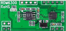
The RDM6300 is a 125 kHz RFID reader module designed for reading RFID tags. It is a compact and cost-effective solution for integrating RFID functionality into various projects. The module communicates via a serial interface, making it easy to interface with microcontrollers such as Arduino, Raspberry Pi, and other embedded systems.
Explore Projects Built with RDM6300


Explore Projects Built with RDM6300
Common Applications and Use Cases
- Access control systems
- Attendance tracking
- Inventory management
- Smart lockers and vending machines
- Embedded systems requiring RFID functionality
Technical Specifications
The RDM6300 module is designed to operate efficiently in a variety of environments. Below are its key technical details:
| Parameter | Specification |
|---|---|
| Operating Frequency | 125 kHz |
| Operating Voltage | 4.5V - 5.5V |
| Current Consumption | ~50 mA |
| Communication Protocol | UART (Serial) |
| Baud Rate | 9600 bps |
| Reading Distance | Up to 5 cm (depending on tag type) |
| Supported Tags | EM4100 and compatible 125 kHz tags |
| Dimensions | 38 mm x 19 mm x 9 mm |
Pin Configuration and Descriptions
The RDM6300 module has a total of 4 pins. Below is the pinout and description:
| Pin | Name | Description |
|---|---|---|
| 1 | VCC | Power supply input (4.5V - 5.5V) |
| 2 | GND | Ground connection |
| 3 | TX | Serial data output (connect to RX of microcontroller) |
| 4 | ANT | Antenna connection (pre-soldered on the module) |
Usage Instructions
How to Use the RDM6300 in a Circuit
- Power the Module: Connect the
VCCpin to a 5V power source and theGNDpin to ground. - Connect to a Microcontroller:
- Connect the
TXpin of the RDM6300 to theRXpin of your microcontroller (e.g., Arduino). - Ensure the microcontroller's UART baud rate is set to 9600 bps.
- Connect the
- Place an RFID Tag: Position a 125 kHz RFID tag within 5 cm of the module's antenna to read its unique ID.
- Read Data: The module will output the tag's ID as a 12-byte ASCII string via the
TXpin.
Important Considerations and Best Practices
- Power Supply: Ensure a stable 5V power supply to avoid communication errors.
- Antenna Placement: Avoid placing the module near metal objects or other sources of electromagnetic interference, as this can reduce reading distance.
- Tag Compatibility: Use only 125 kHz RFID tags that are compatible with the EM4100 standard.
- Serial Communication: If using the module with a 3.3V microcontroller, use a level shifter to safely interface the 5V
TXsignal.
Example Code for Arduino UNO
Below is an example of how to use the RDM6300 with an Arduino UNO to read RFID tag IDs:
// Example code for interfacing the RDM6300 RFID reader with Arduino UNO
// Connect RDM6300 TX to Arduino RX (Pin 0), VCC to 5V, and GND to GND.

void setup() {
  Serial.begin(9600); // Initialize serial communication at 9600 bps
  Serial.println("RDM6300 RFID Reader Ready");
}

void loop() {
  if (Serial.available() > 0) {
    // Check if data is available from the RDM6300
    String tagID = ""; // Variable to store the RFID tag ID
    while (Serial.available() > 0) {
      char c = Serial.read(); // Read one character at a time
      tagID += c; // Append the character to the tag ID string
      delay(5); // Small delay to ensure all characters are read
    }
    Serial.print("RFID Tag ID: ");
    Serial.println(tagID); // Print the tag ID to the Serial Monitor
  }
}
Troubleshooting and FAQs
Common Issues and Solutions
No Data Received from the Module
- Cause: Incorrect wiring or baud rate mismatch.
- Solution: Double-check the connections, ensuring the
TXpin of the RDM6300 is connected to theRXpin of the microcontroller. Verify that the baud rate is set to 9600 bps.
Short Reading Distance
- Cause: Interference from nearby metal objects or poor power supply.
- Solution: Move the module away from metal objects and ensure a stable 5V power supply.
Unreadable or Corrupted Data
- Cause: Noise on the serial line or incorrect tag type.
- Solution: Use shielded cables for longer connections and ensure the tag is compatible with the EM4100 standard.
Module Overheating
- Cause: Excessive current draw or incorrect voltage.
- Solution: Ensure the input voltage is within the 4.5V - 5.5V range and check for any short circuits.
FAQs
Q: Can the RDM6300 read 13.56 MHz RFID tags?
A: No, the RDM6300 is designed specifically for 125 kHz RFID tags and is not compatible with 13.56 MHz tags.
Q: How many tags can the RDM6300 read simultaneously?
A: The RDM6300 can only read one tag at a time. If multiple tags are present, it may not function correctly.
Q: Can I extend the antenna for a longer reading range?
A: Extending the antenna is not recommended, as it may affect the module's performance and reliability.