How to Use PV Isolator: Examples, Pinouts, and Specs
Introduction
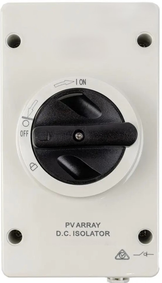
A PV isolator is a critical safety component used in photovoltaic (solar power) systems. It is a manually operated switch designed to disconnect the solar panels from the inverter or the grid. This disconnection ensures that maintenance or emergency procedures can be carried out safely, without the risk of electric shock or damage to the system. PV isolators are typically installed between the solar array and the inverter, and they are essential for compliance with safety standards in solar installations.
Explore Projects Built with PV Isolator


Explore Projects Built with PV Isolator
Common Applications and Use Cases
- Disconnecting solar panels during maintenance or repair of the inverter or other system components.
- Isolating the photovoltaic system in case of emergencies, such as electrical faults or fire.
- Ensuring compliance with safety regulations in residential, commercial, and industrial solar installations.
Technical Specifications
Below are the key technical details of a typical PV isolator:
| Parameter | Value |
|---|---|
| Rated Voltage | 600V DC to 1000V DC (varies by model) |
| Rated Current | 16A to 32A (varies by model) |
| Poles | 2-pole or 4-pole configurations |
| Operating Temperature | -25°C to +70°C |
| Protection Rating | IP65 (weatherproof for outdoor use) |
| Mounting Type | DIN rail or surface-mounted |
| Compliance Standards | IEC 60947-3, AS/NZS 5033 |
Pin Configuration and Descriptions
PV isolators do not have traditional "pins" like ICs or connectors. Instead, they feature input and output terminals for connecting the solar array and inverter. Below is a description of the terminal configuration:
| Terminal | Description |
|---|---|
| Input (+) | Positive terminal for connecting the solar array. |
| Input (-) | Negative terminal for connecting the solar array. |
| Output (+) | Positive terminal for connecting to the inverter. |
| Output (-) | Negative terminal for connecting to the inverter. |
Usage Instructions
How to Use the PV Isolator in a Circuit
Placement in the Circuit:
- Install the PV isolator between the solar panel array and the inverter.
- Ensure that the isolator is easily accessible for manual operation.
Wiring:
- Connect the positive and negative terminals of the solar array to the input terminals of the isolator.
- Connect the output terminals of the isolator to the corresponding input terminals of the inverter.
- Tighten all connections securely to prevent loose contacts.
Operation:
- To disconnect the solar array, turn the isolator switch to the "OFF" position.
- To reconnect the solar array, turn the switch back to the "ON" position.
Important Considerations and Best Practices
- Safety First: Always ensure the PV isolator is in the "OFF" position before performing any maintenance on the system.
- Voltage Rating: Verify that the isolator's voltage and current ratings match the specifications of your solar system.
- Weatherproofing: For outdoor installations, ensure the isolator has an IP65 or higher rating to protect against dust and water ingress.
- Compliance: Install the isolator in accordance with local electrical codes and standards.
Example: Connecting a PV Isolator to an Arduino UNO
While PV isolators are not typically connected to microcontrollers like the Arduino UNO, you can use an Arduino to monitor the state of the isolator (e.g., whether it is ON or OFF) using a digital input pin. Below is an example code snippet:
// Define the digital pin connected to the PV isolator's state indicator
const int isolatorPin = 2;

void setup() {
  pinMode(isolatorPin, INPUT); // Set the pin as an input
  Serial.begin(9600); // Initialize serial communication
}

void loop() {
  int isolatorState = digitalRead(isolatorPin); // Read the isolator state

  if (isolatorState == HIGH) {
    // If the pin reads HIGH, the isolator is ON
    Serial.println("PV Isolator is ON. System is connected.");
  } else {
    // If the pin reads LOW, the isolator is OFF
    Serial.println("PV Isolator is OFF. System is disconnected.");
  }

  delay(1000); // Wait for 1 second before reading again
}
Note: This example assumes the PV isolator has a built-in state indicator or auxiliary contact that can be connected to the Arduino.
Troubleshooting and FAQs
Common Issues and Solutions
| Issue | Solution |
|---|---|
| The isolator does not disconnect the circuit. | Ensure the switch is fully turned to the "OFF" position. Check for damaged contacts. |
| Loose or overheating connections. | Verify that all terminals are securely tightened. Use appropriate wire sizes. |
| Water ingress in outdoor installations. | Ensure the isolator has an IP65 or higher rating and is properly sealed. |
| Incorrect voltage or current rating. | Replace the isolator with one that matches the system's specifications. |
FAQs
Can I use a PV isolator for AC circuits?
No, PV isolators are specifically designed for DC circuits in photovoltaic systems. For AC circuits, use an appropriate AC isolator.How often should I inspect the PV isolator?
It is recommended to inspect the isolator during routine maintenance of the solar system, typically once or twice a year.What happens if the isolator is left in the "OFF" position?
The solar array will remain disconnected from the inverter, and no power will be supplied to the system.Can I install the PV isolator indoors?
Yes, but ensure it is easily accessible and complies with local safety regulations. For outdoor installations, use a weatherproof model.
By following this documentation, you can safely and effectively use a PV isolator in your photovoltaic system.