Cirkit Designer Logo
Cirkit Designer
Your all-in-one circuit design IDE
Home / 
Component Documentation

How to Use Adafruit 16x8 LED Matrix Backpack Yellow-Green: Examples, Pinouts, and Specs

Image of Adafruit 16x8 LED Matrix Backpack Yellow-Green
Cirkit Designer LogoDesign with Adafruit 16x8 LED Matrix Backpack Yellow-Green in Cirkit Designer

Introduction

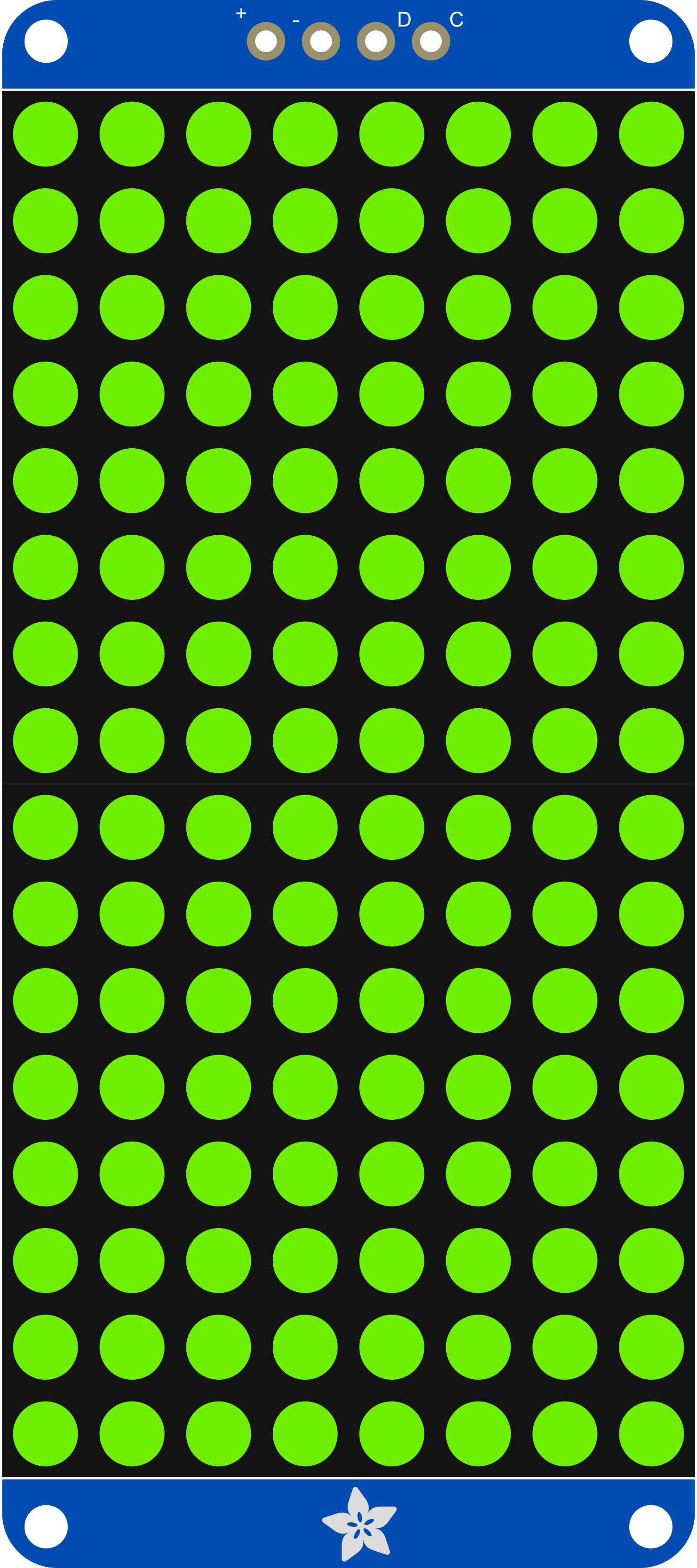
The Adafruit 16x8 LED Matrix Backpack Yellow-Green is a compact and versatile display module that allows users to add a bright, eye-catching display to their projects. This LED matrix has 16 columns and 8 rows, providing a total of 128 LEDs in a yellow-green color. It is designed for ease of use and can be controlled via I2C, making it an excellent choice for displaying numbers, letters, and simple graphics. Common applications include wearable electronics, status indicators, message boards, and time displays.

Explore Projects Built with Adafruit 16x8 LED Matrix Backpack Yellow-Green

Use Cirkit Designer to design, explore, and prototype these projects online. Some projects support real-time simulation. Click "Open Project" to start designing instantly!
Arduino UNO Controlled LED Matrix and LCD Interface with Joystick Interaction
Image of Digital Game Circuit: A project utilizing Adafruit 16x8 LED Matrix Backpack Yellow-Green in a practical application
This circuit features an Arduino UNO microcontroller interfaced with an 8x8 LED matrix, an LCD screen, and a KY-023 Dual Axis Joystick Module. The Arduino controls the LED matrix via digital pins D10-D12 and powers the matrix, LCD, and joystick module from its 5V output. The joystick's analog outputs are connected to the Arduino's analog inputs A0 and A1 for position sensing, while the LCD is controlled through digital pins D2-D6 and D13 for display purposes.
Cirkit Designer LogoOpen Project in Cirkit Designer
ESP32-Controlled Dual 8x8 LED Matrix Display with NTP Time Synchronization
Image of time: A project utilizing Adafruit 16x8 LED Matrix Backpack Yellow-Green in a practical application
This circuit features an ESP32 microcontroller connected to two cascaded 8x8 LED matrix displays, powered by a 3.3V battery. The ESP32 drives the displays to show time and other information, with the code indicating functionality for connecting to WiFi, synchronizing time via NTP, and displaying data on the matrices using custom fonts. Additionally, there is a separate 3.3V battery powering a red LED, which appears to function as a simple indicator light.
Cirkit Designer LogoOpen Project in Cirkit Designer
Arduino UNO Controlled Interactive Display with Joystick and Buzzer Feedback
Image of joystick: A project utilizing Adafruit 16x8 LED Matrix Backpack Yellow-Green in a practical application
This circuit features an Arduino UNO microcontroller connected to an 8x8 LED matrix, an LCD display with I2C interface, a KY-023 Dual Axis Joystick Module, and a Piezo Buzzer. The Arduino controls the LED matrix via digital pins and provides an interface for the joystick's analog inputs and button press. The LCD display is used for output, and the buzzer is driven by a digital pin for audio feedback.
Cirkit Designer LogoOpen Project in Cirkit Designer
Arduino-Controlled RGB LED Matrix Display
Image of SMD2121 Led screen: A project utilizing Adafruit 16x8 LED Matrix Backpack Yellow-Green in a practical application
This circuit connects an Arduino UNO R4 WiFi microcontroller to a 64x32 LED matrix display. The Arduino is configured to control the LED matrix, sending color data and control signals to display various colors across the matrix. The embedded code on the Arduino cycles through a range of colors, filling the entire LED matrix with each color in sequence.
Cirkit Designer LogoOpen Project in Cirkit Designer

Explore Projects Built with Adafruit 16x8 LED Matrix Backpack Yellow-Green

Use Cirkit Designer to design, explore, and prototype these projects online. Some projects support real-time simulation. Click "Open Project" to start designing instantly!
Image of Digital Game Circuit: A project utilizing Adafruit 16x8 LED Matrix Backpack Yellow-Green in a practical application
Arduino UNO Controlled LED Matrix and LCD Interface with Joystick Interaction
This circuit features an Arduino UNO microcontroller interfaced with an 8x8 LED matrix, an LCD screen, and a KY-023 Dual Axis Joystick Module. The Arduino controls the LED matrix via digital pins D10-D12 and powers the matrix, LCD, and joystick module from its 5V output. The joystick's analog outputs are connected to the Arduino's analog inputs A0 and A1 for position sensing, while the LCD is controlled through digital pins D2-D6 and D13 for display purposes.
Cirkit Designer LogoOpen Project in Cirkit Designer
Image of time: A project utilizing Adafruit 16x8 LED Matrix Backpack Yellow-Green in a practical application
ESP32-Controlled Dual 8x8 LED Matrix Display with NTP Time Synchronization
This circuit features an ESP32 microcontroller connected to two cascaded 8x8 LED matrix displays, powered by a 3.3V battery. The ESP32 drives the displays to show time and other information, with the code indicating functionality for connecting to WiFi, synchronizing time via NTP, and displaying data on the matrices using custom fonts. Additionally, there is a separate 3.3V battery powering a red LED, which appears to function as a simple indicator light.
Cirkit Designer LogoOpen Project in Cirkit Designer
Image of joystick: A project utilizing Adafruit 16x8 LED Matrix Backpack Yellow-Green in a practical application
Arduino UNO Controlled Interactive Display with Joystick and Buzzer Feedback
This circuit features an Arduino UNO microcontroller connected to an 8x8 LED matrix, an LCD display with I2C interface, a KY-023 Dual Axis Joystick Module, and a Piezo Buzzer. The Arduino controls the LED matrix via digital pins and provides an interface for the joystick's analog inputs and button press. The LCD display is used for output, and the buzzer is driven by a digital pin for audio feedback.
Cirkit Designer LogoOpen Project in Cirkit Designer
Image of SMD2121 Led screen: A project utilizing Adafruit 16x8 LED Matrix Backpack Yellow-Green in a practical application
Arduino-Controlled RGB LED Matrix Display
This circuit connects an Arduino UNO R4 WiFi microcontroller to a 64x32 LED matrix display. The Arduino is configured to control the LED matrix, sending color data and control signals to display various colors across the matrix. The embedded code on the Arduino cycles through a range of colors, filling the entire LED matrix with each color in sequence.
Cirkit Designer LogoOpen Project in Cirkit Designer

Technical Specifications

Key Technical Details

  • Display Color: Yellow-Green
  • Matrix Size: 16 columns x 8 rows (128 LEDs)
  • Operating Voltage: 4.5V - 5.5V
  • Max Current (with all LEDs on): 320mA
  • Communication: I2C interface
  • I2C Addresses: 0x70 (default) - 0x77 (selectable with solder jumpers)
  • Dimensions: 1.2" x 2.7" x 0.1" (31mm x 70mm x 2.5mm)

Pin Configuration and Descriptions

Pin Description
GND Ground connection
VCC Power supply (4.5V - 5.5V)
SDA I2C Data line
SCL I2C Clock line
ADDR Address selection (connect to GND or VCC to change address)

Usage Instructions

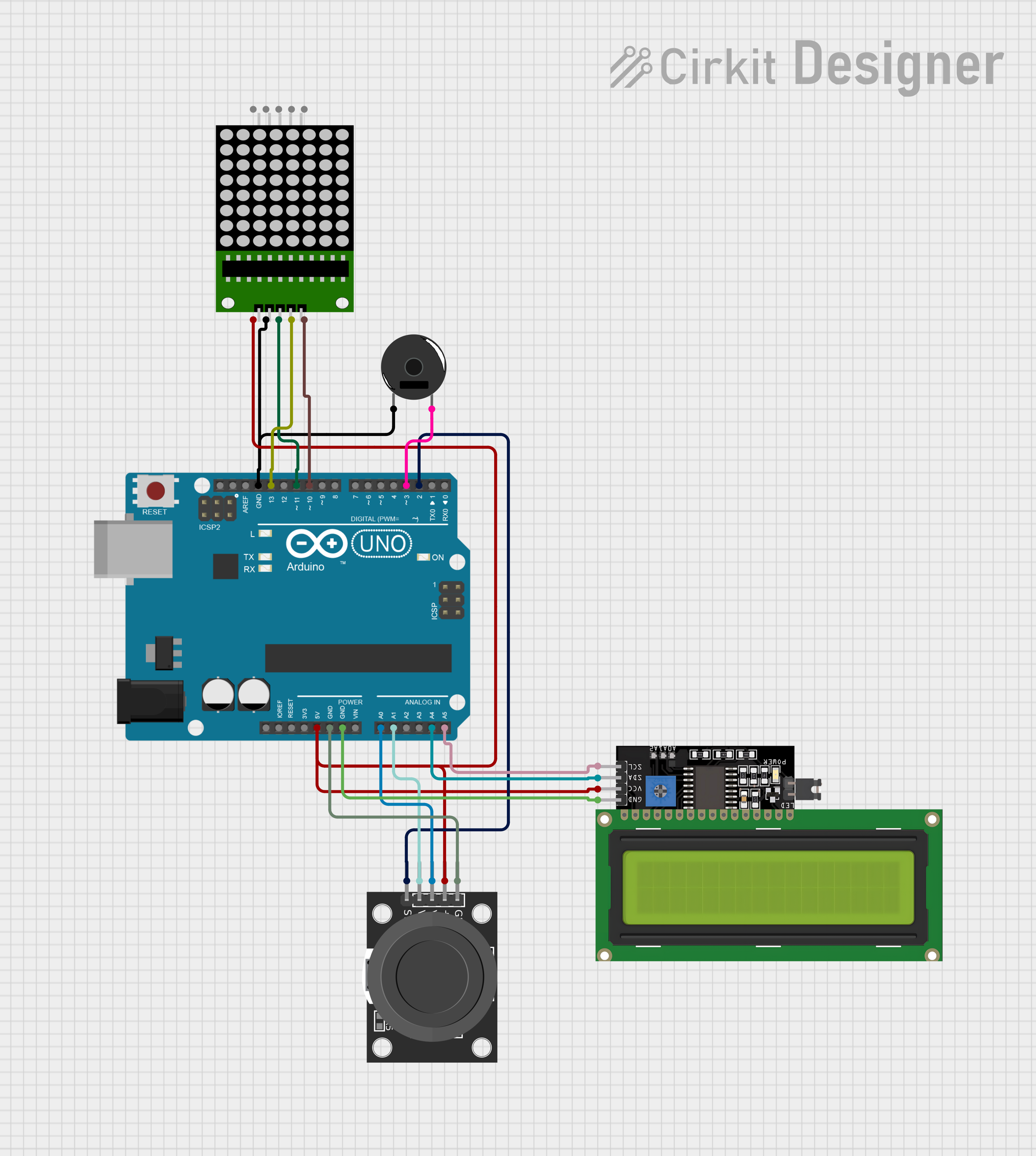
Connecting to an Arduino UNO

  1. Power Connections:

    • Connect the VCC pin to the 5V output on the Arduino.
    • Connect the GND pin to one of the GND pins on the Arduino.
  2. I2C Connections:

    • Connect the SDA pin to the A4 pin on the Arduino (SDA).
    • Connect the SCL pin to the A5 pin on the Arduino (SCL).
  3. Address Selection:

    • The ADDR pin can be connected to GND or VCC to change the I2C address if multiple displays are used.

Programming the Display

To control the LED matrix, you can use the Adafruit LED Backpack library available through the Arduino Library Manager. Here is a simple example code to get started:

#include <Wire.h>
#include <Adafruit_GFX.h>
#include <Adafruit_LEDBackpack.h>

Adafruit_8x16matrix matrix = Adafruit_8x16matrix();

void setup() {
  matrix.begin(0x70); // Start the display at I2C address 0x70
  matrix.setBrightness(15); // Set brightness to a medium level (0-15)
}

void loop() {
  matrix.clear(); // Clear the display buffer
  matrix.setCursor(0, 0); // Set cursor at top-left corner
  matrix.print("Hello"); // Print "Hello" to the buffer
  matrix.writeDisplay(); // Write the buffer to the display
  delay(2000); // Wait for 2 seconds
  matrix.clear(); // Clear the display for the next message
  matrix.setCursor(0, 0); // Reset cursor position
  matrix.print("World"); // Print "World" to the buffer
  matrix.writeDisplay(); // Update the display
  delay(2000); // Wait for 2 seconds
}

Important Considerations and Best Practices

  • Power Requirements: Ensure that your power supply can handle the maximum current draw when all LEDs are on.
  • Brightness Control: Adjust the brightness to suit your application and to prevent excessive power consumption.
  • I2C Addressing: Use the ADDR pin to set different addresses if using multiple LED matrices on the same I2C bus.

Troubleshooting and FAQs

Common Issues

  • Display Not Lighting Up: Check the power connections and ensure the correct I2C address is used in the code.
  • Garbled Display: Ensure there are no loose connections and that the I2C lines are connected properly.
  • Dim Display: Increase the brightness setting in the code or check the power supply voltage.

Solutions and Tips for Troubleshooting

  • Check Connections: Verify all connections are secure and correct.
  • Use External Power: If using multiple LED matrices, consider using an external power supply.
  • I2C Scanning: Use an I2C scanner sketch to confirm the address of the LED matrix.

FAQs

Q: Can I daisy-chain multiple LED matrices? A: Yes, you can connect multiple matrices by setting unique I2C addresses for each and wiring them in parallel.

Q: How do I change the I2C address? A: Solder or otherwise connect the ADDR pin to GND or VCC and modify the address in your code accordingly.

Q: Can I display images on the matrix? A: The matrix is best suited for displaying text and simple graphics due to its resolution.

For further assistance, consult the Adafruit support forums or the detailed product guides available on the Adafruit website.